A lil' history ...
These are instructions on how to
build the Mini-Flash Controller kit (parts)
Parts & Tools List
...
1) One
(1) PIC 12F683 Chip (preprogrammed with Mini-Flash code)
2) Three (3) 10K ohm resistors (2 for Miniflash, 1 for programming cable)
3) One (1) 2.2K resistor
4) One (1) Servo Lead/Pigtail wire for Mini-Flash
5) One (1) 16 pin (8x2) Dual-Row header (male)
6) Four (4) 2N2222 NPN Transistors
7) One (1) RS-232 9-pin female connector (to connect to PC com port)
8) One (1) RS-232 9-pin Hood/Cover
9) One (1) Programming Cable Wire (i.e. Servo Extension)
10) One (1) Programming cable wire (2 conductor wire, 4' or so)
11) 8 dual-row headers (mating connectors for Mini-Flash Header)
12) 3 pieces of heat shrink tubing for assembly (for Mini-Flash & programming
cable)
(Note: Customer is responsible for
supplying LEDs and connecting wires... LEDs, wire and connectors are sold separately in the
DIYRC webstore)
Building Instructions...
(Some diagrams to refer to during assembly)
 The
Mini-Flash Kit (contents)...
The
Mini-Flash Kit (contents)...
(Programming cable wires, Mini-Flash Controller
parts and RS-232 DB9 shell/case)
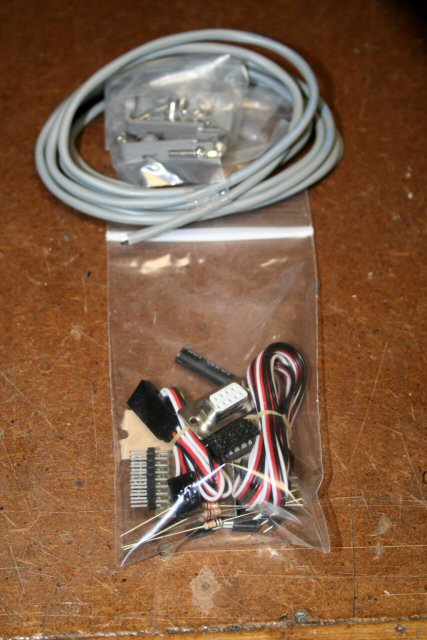
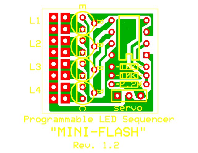
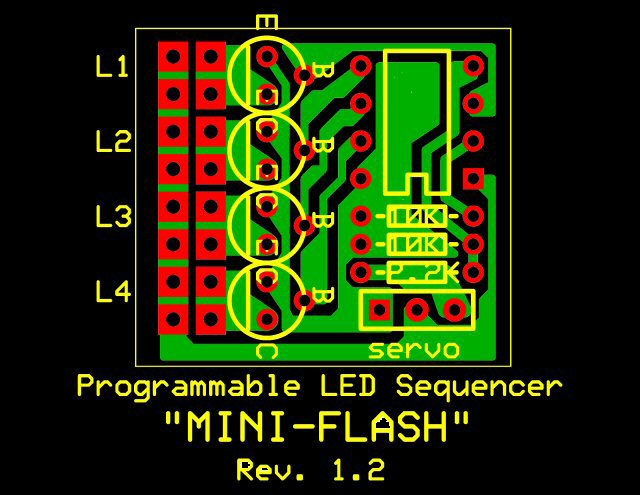
Picture
of the contents for the Mini-Flash controller
Programming/Control servo cable, three 10K resistors, one 2.2K resistor,
pre-programmed PIC chip, four 2N2222 transistors, 16-pin dual row (2x8) header connector,
8 LED connectors and the printed
circuit board (PCB)
(Note: Color of wires supplied might vary)
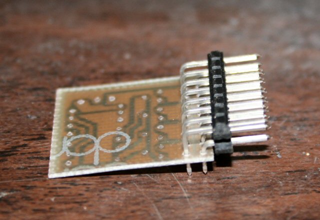
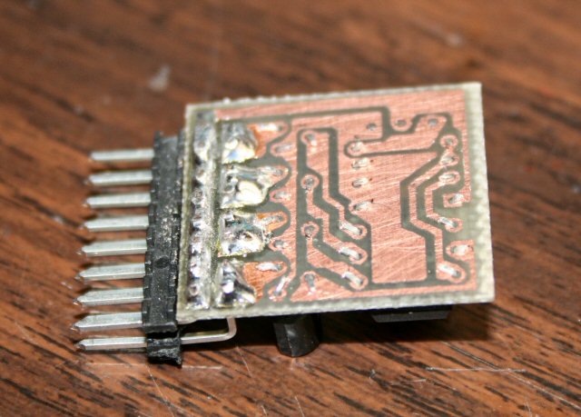
P.C.B.
Assembly:
Soldering the machine pin connector onto the PCB
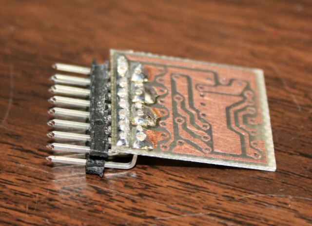
Soldering of the machine pin header completed (use
plenty of solder).
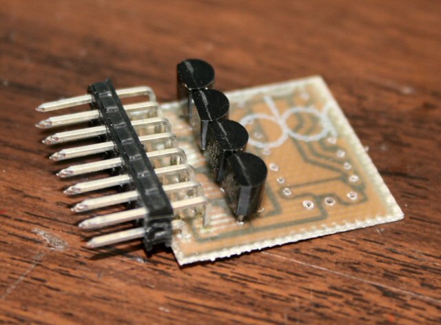
Inserting the transistors one at a time... be sure
flat side of transistor faces the header
After inserting all four (4) transistor, bend over
leads and snip
Be sure transistors are pushed all the way down, so
they touch the PCB
Solder all the transistors in place (don't use too
much heat though)
You could also use a small alligator clip which you
could clip on the transistor to dissipate heat. I always do and never had
a transistor go bad on me when soldering. Use a low wattage iron too (i.e.
25w or so)
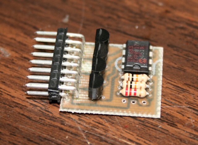
Now, insert the two 10K resistors, the 2.2K
resistor, the PIC and again, bend
and snip all leads.
NOTE: R3 (bottom resistor) is the 2.2K resistor
(other two above this are 10K each)
Notice how the leads are bend down towards the PCB.
This makes for easier soldering.
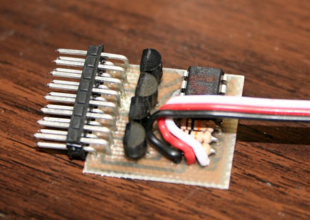
NOTE: Pay close attention to how the leads are
connected to the Mini-Flash. The ground lead (black) is connected closest
to the transistors.
Note: I sometimes supply
different servo leads which have black, red and white wires. On these,
Red=Orange, White=Green and Black=Black.
PIC, resistors and servo wire connections are then soldered. Again use
minimal heat when soldering the PIC connections. You could also use a
small alligator clip which you could clip on the PIC's leads to dissipate heat.
I always do and never had a PIC go bad on me when soldering. Use a low
wattage iron too (i.e. 25w or so)
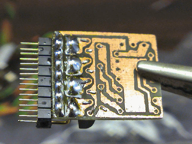
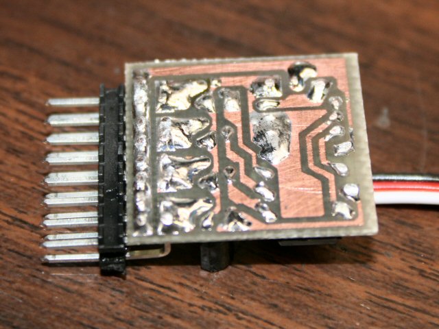
Flip the PCB over and be sure all leads are snipped
and tidy.
I usually then take a small file and file down the
high connections, particularly the header pins that usually stick out a bit.
After filing, it is very important you clean the PCB
completely of any residual solder flux (and metal filings!). I use a high
quality deflux spray and flood the PCB until all traces of flux are gone.
Using a small, stiff bristle brush helps remove the flux too.
The only thing left to do is to apply the included
heat shrink tubing/wrap. Notice how the servo wire is routed
(slight bend/loop). I usually fix the servo wire as shown here with a
little hot melt glue, just to be sure that the wire does not easily pull out.
After applying the hot melt glue, simply slide the tubing over the circuit and
slowly apply heat. Be sure the tubing shrinks just around the black part
of the header. Adjust before fully shrinking the wrap.
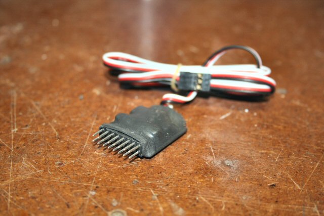
This is what the finished product should look like !
Now it is time to build the programming cable!
Good Job !
Programming Cable Assembly
Refer to the Schematic for the Mini-Flash
Programming Cable
(CLICK HERE!)
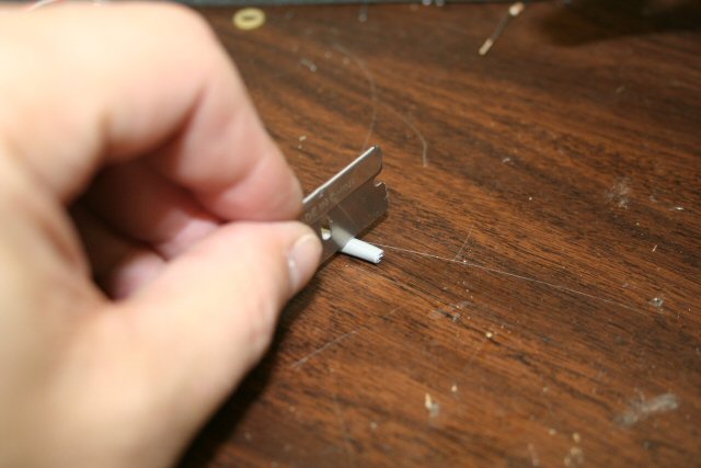
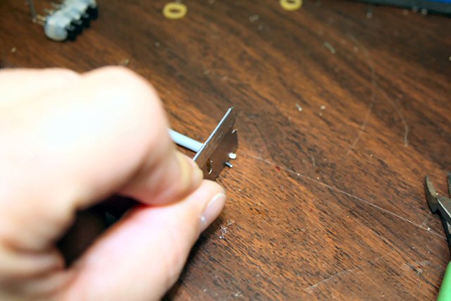
Locate one end of the 2-conductor cable (usually
grey in color) and roll a razor blade over the outer covering (3/4" back from
end). strip the end of each of the wires and tin with a soldering iron.
This end of the cable will connect to the supplied RS-232 9-pin connector.
 One
the other end of the grey cable, strip off insulation 1/2" from the end. Strip
both wires and tin with a soldering iron. This end of the cable will connect to
the Miniflash programming connectors (servo extension).
One
the other end of the grey cable, strip off insulation 1/2" from the end. Strip
both wires and tin with a soldering iron. This end of the cable will connect to
the Miniflash programming connectors (servo extension).
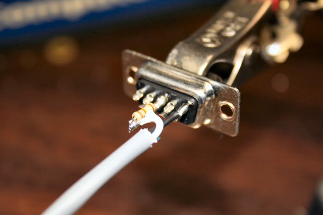 Solder
one end of a 10K resistor to pin#3 (middle pin of row with 5 pins) and snip the
other end of the resistor short (leave 1/8" of lead)
Solder
one end of a 10K resistor to pin#3 (middle pin of row with 5 pins) and snip the
other end of the resistor short (leave 1/8" of lead)
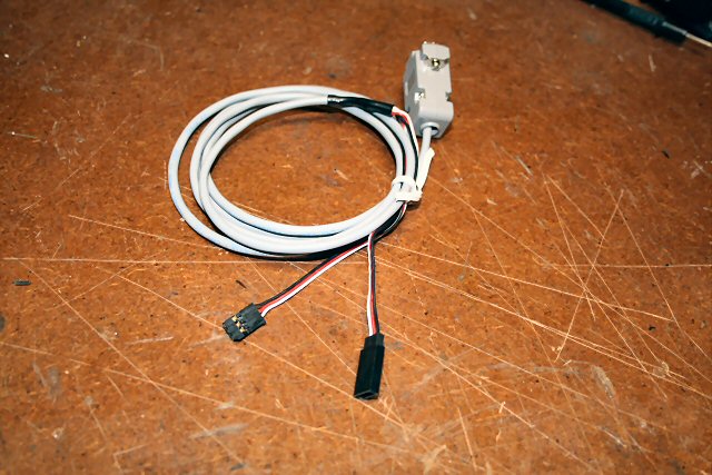
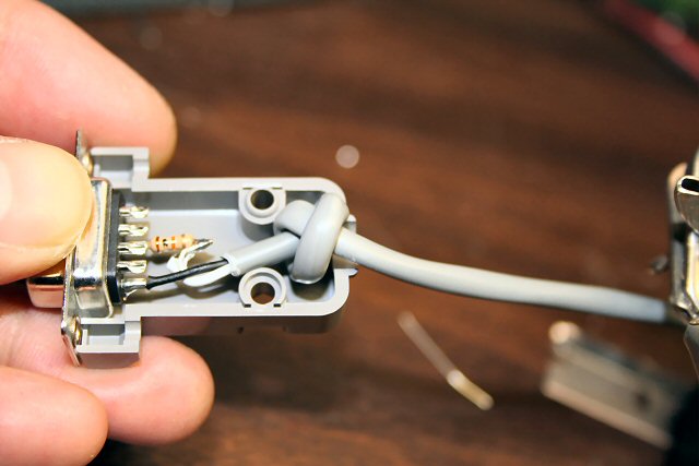 After
soldering the cable wires to the RS-232 connector, tie a knot in the cable, 3/4"
from the end of the grey insulation such that it will neatly fit in the supplied
RS-232 shell as shown.
After
soldering the cable wires to the RS-232 connector, tie a knot in the cable, 3/4"
from the end of the grey insulation such that it will neatly fit in the supplied
RS-232 shell as shown.
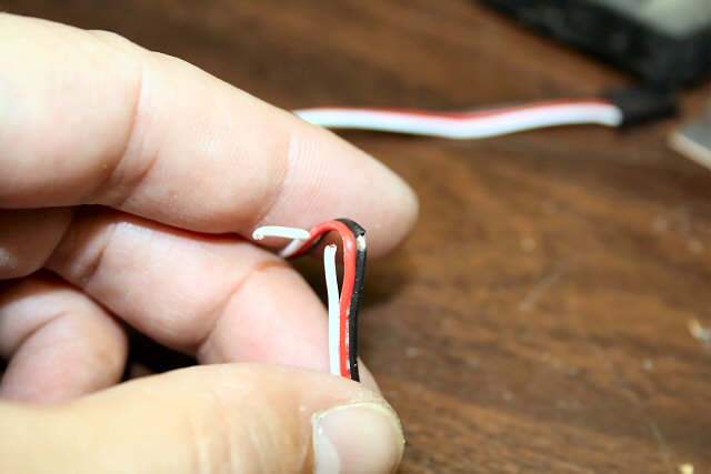
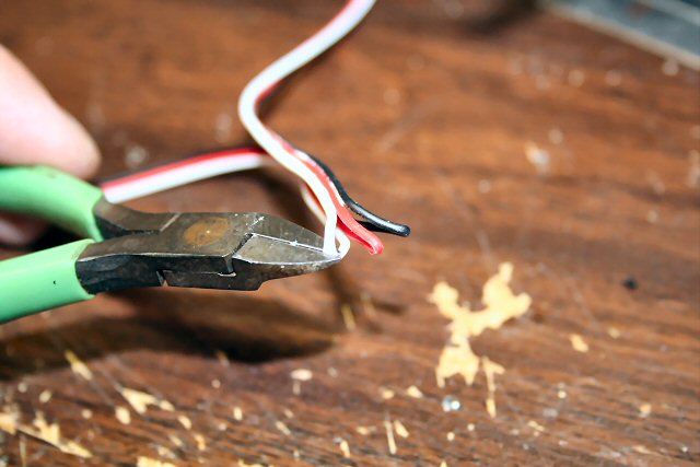 Locate
the servo extension supplied with the kit and locate the middle of the wire (fold in half).
Then, snip the white (servo signal) wire. Leave the black and red wires
intact.
Locate
the servo extension supplied with the kit and locate the middle of the wire (fold in half).
Then, snip the white (servo signal) wire. Leave the black and red wires
intact.
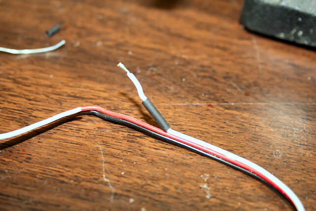
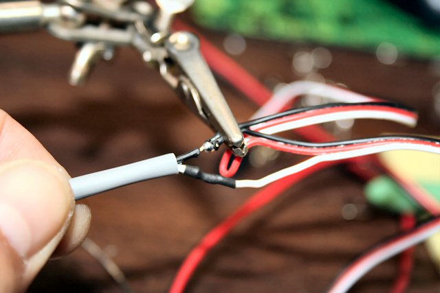
 In
the middle of the black (ground) wire, gently scrape off some insulation so the
copper wire is slightly exposed (as shown) and tin this exposed wire/area.
In
the middle of the black (ground) wire, gently scrape off some insulation so the
copper wire is slightly exposed (as shown) and tin this exposed wire/area.
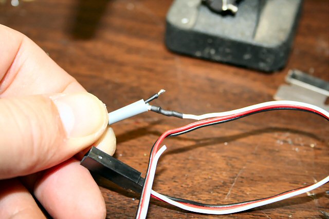
Locate the servo extension end (female) that will
mate with the Miniflash. Follow the white wire and strip and tin this
wire.
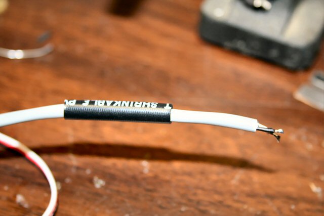
 Slide
the thin piece of supplied heat shrink tubing onto the white servo wire
previously tinned
Slide
the thin piece of supplied heat shrink tubing onto the white servo wire
previously tinned
Again, be sure this white wire leads back to the servo
connector end (female) that will accept the Miniflash cable end (Male)
 Slide
the larger piece of heat shrink tubing onto the grey cable
Slide
the larger piece of heat shrink tubing onto the grey cable
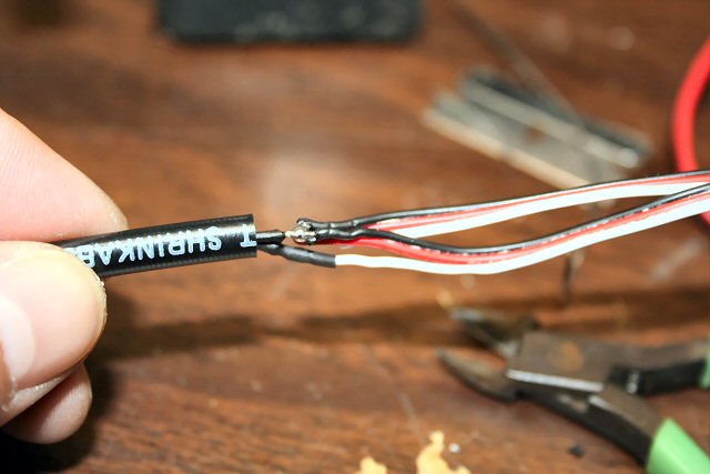
 Solder
the white wire of the grey cable onto the tinned white wire of the servo connector.
Slide the heat shrink tubing over this connection and heat/shrink
Solder
the white wire of the grey cable onto the tinned white wire of the servo connector.
Slide the heat shrink tubing over this connection and heat/shrink
 Now,
solder the black wire of the grey cable onto the exposed black wired on the
servo connector.
Now,
solder the black wire of the grey cable onto the exposed black wired on the
servo connector.
 Gather
all the wires together and then slide the heat shrink tubing over these
connections.
Gather
all the wires together and then slide the heat shrink tubing over these
connections.
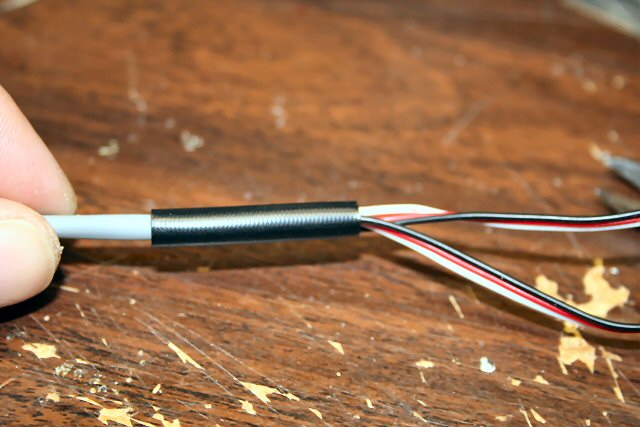 Heat
and shrink this connection and you will then be done!
Heat
and shrink this connection and you will then be done!
YOU ARE NOW DONE!
TIME TO TEST !
NOTE: If you do not have a serial port on your
computer, most
USB-to-Serial Converters work too...
Click here to see a
verified list
Testing and Operation Instructions...
 VIEW
THE USER'S MANUAL FOR THE MINI-FLASH
VIEW
THE USER'S MANUAL FOR THE MINI-FLASH
 DOWNLOAD THE MINI-FLASH PROGRAMMING
SOFTWARE !
* Click Here *
MINI-FLASH FAQ
Q1. How do you compensate for
differing forward voltages and current drawn by differing LED's?
A1. Ah.... good question....
The input voltage to LEDs is all not that important (usually 5v is fine for
all). It is the current that you push through the LED that is important, as you
do not want to drive them with too much current. You usually always need to put
a seriers resistor inline with one of the LED leads such to limit the current. I
use a neat calculator, I even have a link for it on my webpages. You really need
to know the specs on the LEDs, particularly the LEDs rated current (typical 5mm
LEDs run around 20-25 millimaps). Here's the calculator:
http://linear1.org/ckts/led.php
You simply enter the supply voltage (in the
controller's case, 5 volts), the LEDs forward voltage (this varies from LED to
LED) then enter the rated LED current (typically 20-25 millimaps). Then hit the
"find R" button and the program calculates the resistor value you need for that
LED (typically a 68 - 120 ohm resistor is required). Be careful also as there
exists some LED that already have the series resistor incorporated in the LED
(not all that common though). Once the resistor value is determined, I
usually then solder it to the end of one of the LED leads. The wires then
leading from this LED assembly is then connected directly to the controller
using a miniature machine-pin female socket (I will provide at least 8 with
every controller). Putting the series resistors on the PCB would take up
space (unless they were SMD maybe).
Q2. I have a question: So tell me
how you could control different sequences with a TX like a 6102 which is a 6
channel but the 2 extras are more like landing gear, and flaps?
A2. Great question.... ( I knew I'd eventually have
write about this, as most will probably use a switch and some will have the
luxury of having a spare variable channel, like a rotating knob or lever).
Is the landing gear channel on your system controlled by a switch ? (most
likely). How about the flaps, are these a switch too or is this a rotating knob
(like I think my Futaba 9C has) ??
If the channel you have the flasher plugged into is controlled (Tx) using a
toggle switch, you will still be able to control the 4 LED channels/sequences,
but you will only have two possible servo control positions, on (*---) and off
(---*). If you were to look at the "Servo Control" pull-down in the
software, you have 16 different "servo zone" combinations you can chose. All 16
work only when you are using a variable Rx channel, such as a channel being
controlled by a knob, slider or stick. If you are only using a "switched" Rx
channel and you want to simply use the switch to turn the channel on or off, you
would set up the "servo control" such that it is "*---". What this would do is
make the selected LED channel active only when the switch is in the down
position (actually, it is as if the stick is in the position, 0->1/4
deflection). Now catch this, if you were to choose the "**--" option or the
"***-" option, this would still have the same effect. When using a toggle
switch on your Tx to control the LED flasher, the receiver will never
output the middle two zones (-**-). Therefore selecting these zones in a
channel's servo zone will do nothing.
Q3. I do not have a RS-232 port
on my laptop/computer!
What can I do now?
A3. No Problem! You can use an USB-to-Serial
converter that plugs into a spare USB port on your computer. On the other
end of the cable is a female RS-232 connector you plug the Mini-Flash
programming cable into.
CLICK HERE TO VIEW A
LIST THAT IS KNOWN TO WORK !
TBD
Additional Notes...
 |
TBD
|
|
TBD |
Click Here to visit the


Earthmen
Productions
© Dec-00-Mar-12


