|
|
|||||
|
|
|
|
|
||
|
|
|||||
|
|
|
|
|
||
Note: All pictures that follow are
"clickable". Clicking on them will show you an enlargement!
![]() SEE THE MINI-FLASH
INSTALLED ON A TRAXXAS REVO !!
SEE THE MINI-FLASH
INSTALLED ON A TRAXXAS REVO !!
![]()
![]() NEW
PCM MODIFICATIONS REQUIRED !!
NEW
PCM MODIFICATIONS REQUIRED !!
![]()
(Note: The PCM mod also works with other non-PCM receivers too!)
A lil' history ...
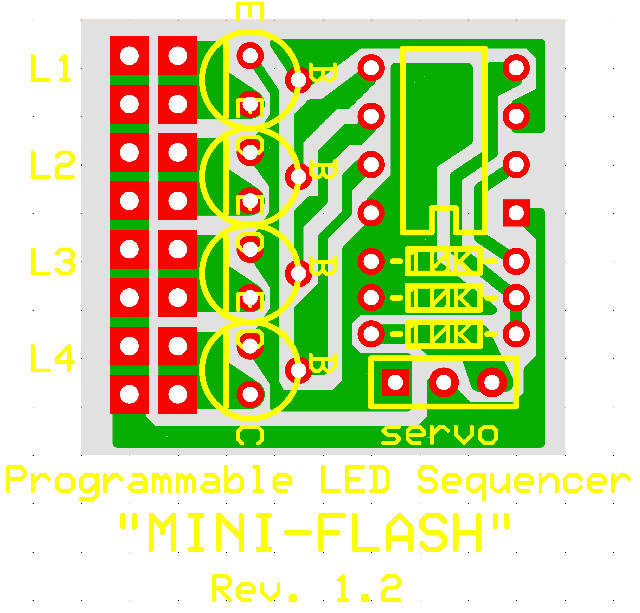
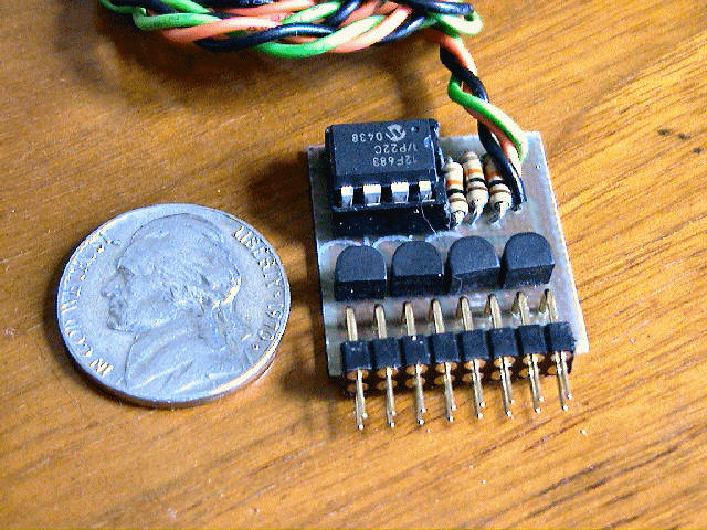 This project, called "Mini-Flash",
is a programmable LED Sequencer/Flasher that is based around the PICAXE 08M microcontroller.
It is basically a spin-off of the
Pro-Flash Programmable LED Flasher/Sequencer which is based around the
larger Picaxe 18X microcontroller. The Mini-Flash sports the same features
as the larger Pro-Flash controller, with the only difference being it can only
control 4 LED channels instead of 8. This neat controller is programmable in a BASIC-like language very similar to
the "Basic Stamp" manufactured by Parallax Inc. This project also includes the ability to
reprogram the LED sequencer using a PC-based (i.e. Windows) program that
includes a unique and intuitive Graphical User Interface. In fact, the
servo lead which is normally plugged into a spare channel for control, is also
used to reprogram the Mini-Flash flasher/sequencer via a computer's serial port
(9-pin) connection and programming cable. The free downloadable programming software
also allows the user to "test" the LED sequence they develop by use of
software-based graphical representations of the 4 LED channels. The
sequence speed can also be programmed by the user. Each sequence contains
50 events and each of the 4 LED channels can be either ON or OFF for every
events. If the user wants to develop a sequence with fewer events, this
can also easily be programmed.
This project, called "Mini-Flash",
is a programmable LED Sequencer/Flasher that is based around the PICAXE 08M microcontroller.
It is basically a spin-off of the
Pro-Flash Programmable LED Flasher/Sequencer which is based around the
larger Picaxe 18X microcontroller. The Mini-Flash sports the same features
as the larger Pro-Flash controller, with the only difference being it can only
control 4 LED channels instead of 8. This neat controller is programmable in a BASIC-like language very similar to
the "Basic Stamp" manufactured by Parallax Inc. This project also includes the ability to
reprogram the LED sequencer using a PC-based (i.e. Windows) program that
includes a unique and intuitive Graphical User Interface. In fact, the
servo lead which is normally plugged into a spare channel for control, is also
used to reprogram the Mini-Flash flasher/sequencer via a computer's serial port
(9-pin) connection and programming cable. The free downloadable programming software
also allows the user to "test" the LED sequence they develop by use of
software-based graphical representations of the 4 LED channels. The
sequence speed can also be programmed by the user. Each sequence contains
50 events and each of the 4 LED channels can be either ON or OFF for every
events. If the user wants to develop a sequence with fewer events, this
can also easily be programmed.
As if these are not enough features, the
"Mini-Flash" also includes a control for each of the 4
channels that allows the user to use an R/C servo output (from a R/C receiver)
as a "switch" control. This feature allows the user to control (active or
inactive) each of the 4 channels in regards to the position of the servo control
input. If the user uses a stick/slider as the servo input, the user will
be able to define one of 16 "Zone" settings for each LED channel.
Read more about the Mini-Flash's operation by viewing the Mini-Flash User's Manual ! (Rev 1)
NEW
- Mini-Flash User's Manual ! (Beta2)
Circuit board dipped !!! Can you say "water proof" ? (made for
a boater who is beta testing the Mini-Flash)
The Mini-Flash below is being built with a standard dual-row .025" square
header, similar to that used by Curtek Lighting systems. I can build your
Mini-Flash with either connectors. Built this way, you can easily plug in
your Curtek LEDs or other assembled LEDs that use standard two-pin servo-type
female connectors. Still, the smaller machine pin connectors I use (shown
above) are lighter and of higher quality.
Mini-Flash Controller and Programming Cable (+ 16
mating LED connectors, Assembled)
Mini-Flash Controller
and Programming Cable (+ 16 mating LED connectors, Kit/Parts)
Design Criteria Summary:
1) Design a simply and cheap programmable LED
flasher around 8-pin PIC
2) Design so LED sequencing speed and sequence pattern is programmable
3) Lightweight and simple to build (diy)
4) Power off of existing R/C servo connector
5) Use servo signal to vary how each LED channel responds (turn programmed
pattern on or off)
6) Design programming software so it's intuitive and provide varying functions
7) Interface to computer using RS-232 (9-pin) connector most computer have...
nothing special
8) Programmable almost indefinitely... change your sequence pattern/speed many,
many times
9) Powers many LEDS (at least 400mA per channel... each typical LED uses
25-40mA)
10) Mini-Flash firmware is upgradeable (through DIYRC only... Free of charge,
you just pay shipping).
1) ...more coming soon
![]() CLICK
HERE TO SEE
THE BUILDING INSTRUCTIONS FOR THE MINI-FLASH KIT !
CLICK
HERE TO SEE
THE BUILDING INSTRUCTIONS FOR THE MINI-FLASH KIT !
![]()
or
![]() PURCHASE
A PREASSEMBLED & TESTED MINI-FLASH NOW!!
PURCHASE
A PREASSEMBLED & TESTED MINI-FLASH NOW!!
![]()
THE PICAXE FIRMWARE FOR THIS PROJECT IS NOT FOR SALE ....
SORRY
Pre-programmed
Picaxe chips are now available !
Click here to purchase
one now!
 DOWNLOAD
THE MINI-FLASH
PROGRAMMING
DOWNLOAD
THE MINI-FLASH
PROGRAMMING
SOFTWARE
!!! (Rev1)
* Click Here *
NEW! - DOWNLOAD
THE MINI-FLASH
PROGRAMMING
SOFTWARE
!!! (Beta2)
* Click Here *
Screen shots of the Mini-Flash programming
software (Rev1).... pretty slick !
Main Screen |
File Menu Screen |
| Loaded Program Screen |
Sequence Testing Screen |
Download Screen #1 |
Download Screen #2 |
Setup Menu (Comm port, Test speed, PIC
speed) |
Help/About Screen |
Help/How-To Screen |
Channel Menu #1 (click on tiny square
button) |
Channel Menu #2 |
LED Color Menu (click on LED text) |
LED Servo Control Menu (select mask) |
Exit Screen |
PROTOTYPE PICTURES !!
Testing and Operation Instructions...
I plan to add more information re: this neat gadget as time allows.
![]() Another
possible "add-on" to these LED flashers (thanks to an email I received) will be
a high current switch option, basically a high current MOSFET that will be
controlled by the flasher's LED output (actually, it plugs into the flasher's
receptor). The MOSFETs switch will use its own power source (i.e., not the
receiver's). This can be used to power glow plugs, high output LEDS,
incandescent lights, motors/pumps, bomb drops (oops, should I have said that?),
and other devices that require high power switching. Stay
tuned...
Another
possible "add-on" to these LED flashers (thanks to an email I received) will be
a high current switch option, basically a high current MOSFET that will be
controlled by the flasher's LED output (actually, it plugs into the flasher's
receptor). The MOSFETs switch will use its own power source (i.e., not the
receiver's). This can be used to power glow plugs, high output LEDS,
incandescent lights, motors/pumps, bomb drops (oops, should I have said that?),
and other devices that require high power switching. Stay
tuned...
MINI-FLASH FAQ
Q1. How do you compensate for differing forward voltages and current drawn by differing LED's?
A1. Ah.... good question....
The input voltage to LEDs is all not that important (usually 5v is fine for
all). It is the current that you push through the LED that is important, as you
do not want to drive them with too much current. You usually always need to put
a series resistor inline with one of the LED leads such to limit the current. I
use a neat calculator, I even have a link for it on my webpages. You really need
to know the specs on the LEDs, particularly the LEDs rated current (typical 5mm
LEDs run around 20-25 milliamps). Here's the calculator:
http://linear1.org/ckts/led.php
You simply enter the supply voltage (in the
controller's case, 5 volts), the LEDs forward voltage (this varies from LED to
LED) then enter the rated LED current (typically 20-25 milliamps). Then hit the
"find R" button and the program calculates the resistor value you need for that
LED (typically a 68 - 120 ohm resistor is required). Be careful also as there
exists some LED that already have the series resistor incorporated in the LED
(not all that common though). Once the resistor value is determined, I
usually then solder it to the end of one of the LED leads. The wires then
leading from this LED assembly is then connected directly to the controller
using a miniature machine-pin female socket (I will provide at least 8 with
every controller). Putting the series resistors on the PCB would take up
space (unless they were SMD maybe).
Q2. I have a question: So tell me how you could control different sequences with a TX like a 6102 which is a 6 channel but the 2 extras are more like landing gear, and flaps?
A2. Great question.... ( I knew I'd eventually have
write about this, as most will probably use a switch and some will have the
luxury of having a spare variable channel, like a rotating knob or lever).
Is the landing gear channel on your system controlled by a switch ? (most
likely). How about the flaps, are these a switch too or is this a rotating knob
(like I think my Futaba 9C has) ??
If the channel you have the flasher plugged into is controlled (Tx) using a
toggle switch, you will still be able to control the 4 LED channels/sequences,
but you will only have two possible servo control positions, on (*---) and off
(---*). If you were to look at the "Servo Control" pull-down in the
software, you have 16 different "servo zone" combinations you can chose. All 16
work only when you are using a variable Rx channel, such as a channel being
controlled by a knob, slider or stick. If you are only using a "switched" Rx
channel and you want to simply use the switch to turn the channel on or off, you
would set up the "servo control" such that it is "*---". What this would do is
make the selected LED channel active only when the switch is in the down
position (actually, it is as if the stick is in the position, 0->1/4
deflection). Now catch this, if you were to choose the "**--" option or the
"***-" option, this would still have the same effect. When using a toggle
switch on your Tx to control the LED flasher, the receiver will never
output the middle two zones (-**-). Therefore selecting these zones in a
channel's servo zone will do nothing.
![]() PCM MODIFICATIONS
PCM MODIFICATIONS
![]()
Q3. I see this works fine with PPM (FM) but... does it also work with Pulse Code Modulation (PCM) ??
A2. Great question.... YES! but with a
few minor mods. See the pictures below
(click on them for enlargements)
PCM is a slightly lower level signal as that for PPM (3 volts versus 4-5 volts).
Because of this, a lower value resister is required on the PCB. Since we
lower the resistor on the PCB, we need to add more resistance to the programming
cable (else too large of an RS-232 signal/current from the PC will be forced
into the PIC).
Basically, we need to change R3 on the PCB from 10K to 2.2K. We then need to add a series 10K resistor inline with the RS-232 signal (in RS-232 shell).

1. TBD
2. TBD
TBD
TBD
**** VERY LIMITED
QUANTITIES ARE AVAILABLE ****
Click Here to visit the
![]()
"PICAXE is a
trademark of Revolution Education Ltd (www.picaxe.co.uk)"