 A lil' history ...
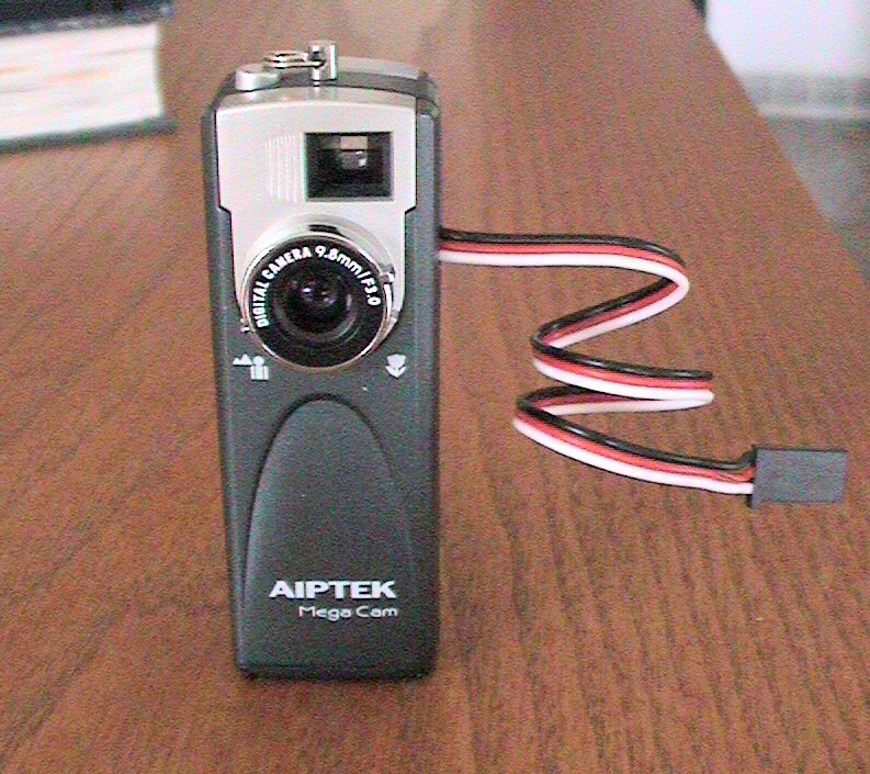
Over a year ago, I
acquired a small miniature digital camera, mainly the
Aiptek 1.3 mega pixel camera. These can still be bought in local
stores such as
Circuit City and other major department stores for $40 or less.
Actually, over the years, I acquired around 8 of these cameras on
Ebay, and if you look long enough and are very patient, you can have one for
under $20 delivered, if not less.
I have received numerous emails from friends and other electronic enthusiasts
regarding the modification of this digital camera for aerial photography use
along with an R/C airplane (preferably electric due to the excessive vibration
of gas-powered planes). One of the easiest methods of modifying the camera
is to simply use an extra servo attached (double-sided tape or even glued) to
the top of the camera, just above the shutter button. This method of orienting the
servo and servo arm such that the servo arm presses the shutter button is
practical but not "clean". It can often be clumsy and can
often malfunction (I have fixed many cameras where the servo arm actually broke
the shutter switch, breaking it from the circuit board, rendering the camera useless).
Another method is to design a simple
electronic circuit that would interface with your R/C receiver and Aiptek
camera. A
simple R/C electronic switch can then be used to remotely trigger the
camera's shutter switch using a spare R/C receiver channel. What would
really be nice though is to have this circuit completely enclosed in the Aiptek
camera, where the only thing exiting the camera would be the servo wire that you
would then
connect to the R/C receiver. Although this might sound easy, the Aiptek
1.3M camera in itself is small. The circuit would therefore have to be
made really small in order to fit comfortably in the Aiptek case. Some
have even designed a neat 8-pin PIC
circuit that is programmed to interface with the receiver servo signal and
the camera's shutter switch. All of the PIC circuit components fit inside the camera case.
Although this might seems like a great idea, even some electronic enthusiasts
tend to shy away from programming PICs. Additionally, PIC circuits (i.e.
oscillators) can generate unwanted EMI, which receivers certainly do not like.
I found this out the hard way a few years back while experimenting.
I therefore wanted to design a simple R/C switch for triggering the Aiptek
shutter switch using ordinary components you can buy at your local electronic
store (i.e. Radio Shack). Also, in order to save weight, I wanted to
design it such that the camera would be powered from the connector going to the
R/C receiver. Most R/C receivers are powered from a battery source which
is typically 4 or 5 cells (4.8v - 6 v). On some electric R/C airplanes,
receivers are typically powered from electronic speed controllers (ESC) which
usually contain a battery elimination circuit (BEC). In either case, this
receiver voltage could be tapped in order to power the camera. Although
the Aiptek camera uses two (2) AA batteries (3 volts), the camera can also be
powered from the Universal Serial Bus (USB) connector. Powering the camera
with batteries works well but if you do not take a picture after a short time,
the camera will automatically shut itself down, requiring you to reactivate
(tough to do when it is in the air). I therefore decided to design the
circuit such that it is powered from the USB connector (the Aiptek camera stays on as long as it is powered
via the
USB connector).
Another design criteria I
wanted is the ability to use the camera "stand-alone", that is, I wanted to be
able to simply pull the camera off my plane, stick a couple of batteries in it
and still be able to take pictures manually.
Design Criteria Summary:
1) Power camera using R/C receiver power
2) Trigger camera shutter switch using spare R/C receiver servo channel
3) Allow use of batteries and allow full, manual operation of camera
4) Design circuit using ordinary parts (i.e. no PICs/programmer or special ICs)
5) Circuit must fit inside existing camera case
OK,... so here we go...... (glad you made it this far.....)
Parts & Tools List
...
1) Aiptek 1.3 mega -pixel
camera
2) 4013 Dual D flip-flop Integrated Circuit (DIP) (Click
here for Datasheet)
3) 22nF (.022uF) Capacitor (the smaller, the better)
4) Two - 100K resistor (again, the smaller, the better.
One might have to be a SMD version)
5) 1N4148 Diode
6) Tiny (28+ gauge?) hookup wires
7) Razor blade or file for trimming case for servo wire
8) Servo hookup wire (w/ male end for connecting to R/C receiver)
9) Soldering iron (1/16" tip) + solder
10) Snippers, pliers, tiny Philips screwdriver, Magnifying glass (if your eyes
are not up to par), etc...
11) Patience! (most important!)
That's it!
If it does not sound like a lot, it isn't! Probably less than $4 worth of
parts.
Building Instructions...
This simple circuit is based upon the
4013 dual D flip-flop
IC and requires only 4 additional passive components (1 cap,
2 resistor and 1
diode). If you want to read about how the circuit actually
operates, see Ken Hewitt's
webpage (the original designer of the circuit). The value of this resistor was chosen such that the "switch
toggle" occurs roughly around the center position of the transmitter stick
(~1.5ms).
This will also allow you to toggle the switch output using a switch on your
transmitter. Depending of your setup (and whether your transmitter allows
you to reverse servo directions), you can either use pin 12 or 13 on the IC (one
is inverse of the other). A diode is also used to interface to the
camera's shutter switch (it acts as a one way "valve", allowing the R/C switch
to control the shutter, while still allowing full manual operation of the
shutter switch. A 100K pull-down resistor was also
added to the servo input lead and ground so as to not allow the input to float
when unplugged from the R/C receiver.
 On
the left is a circuit schematic for the R/C
switch.
On
the left is a circuit schematic for the R/C
switch.
The toughest part of this whole project is assembling the R/C
switch
circuit. The idea is to make it as small and compact as possible.
The smaller, the better. The following pictures and text will guide you
through every step of this process.
We'll first open up the camera and make the necessary
modifications/wiring before building the switch circuit.
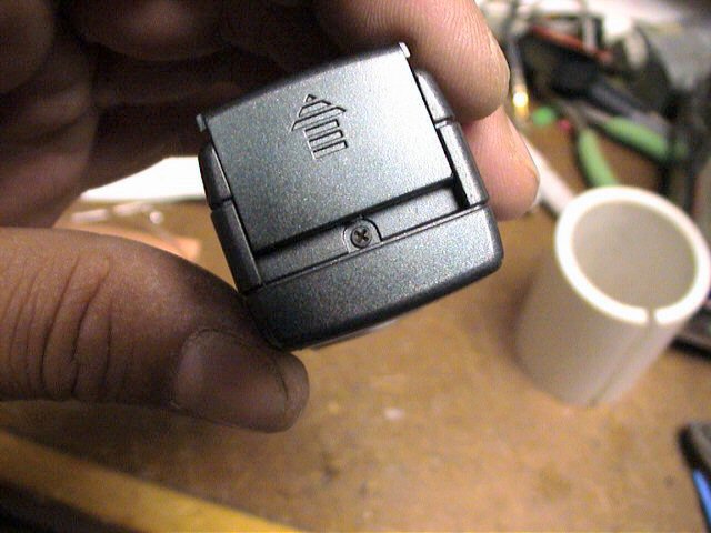 Open
the battery compartment door slightly until you can see the
retaining screw and remove with a small
Philips screwdriver (a magnetized one will save you lots of trouble (such as
loosing the tiny irreplaceable screw). Once this screw is removed, the top
case section can usually be removed from the camera by gently running your
finger nail along the seam. It might take a bit of fussing but for the
most part, it comes off in a "snap".
Open
the battery compartment door slightly until you can see the
retaining screw and remove with a small
Philips screwdriver (a magnetized one will save you lots of trouble (such as
loosing the tiny irreplaceable screw). Once this screw is removed, the top
case section can usually be removed from the camera by gently running your
finger nail along the seam. It might take a bit of fussing but for the
most part, it comes off in a "snap".
NOTE: Before removing the top case section, adjust
the lens focus such that it is set for infinity (clockwise). Remember this
as when you replace the top case section, you can be assured that the focus
setting is retained. Also, once the top case section is removed, be sure
not to touch the focus lens. Doing so will alter the correct focus and
will require unnecessary refocusing.
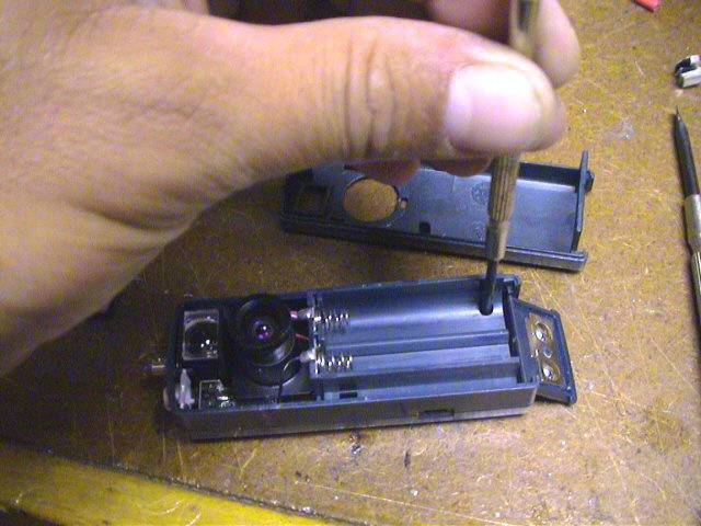
Next, using a small Philips screw driver,
remove the two screws attaching the
middle case section to the bottom case section. Again, be careful not to
loose these screws (I use a magnet attached to my workbench to retain these tiny
screws.... never lost one since).
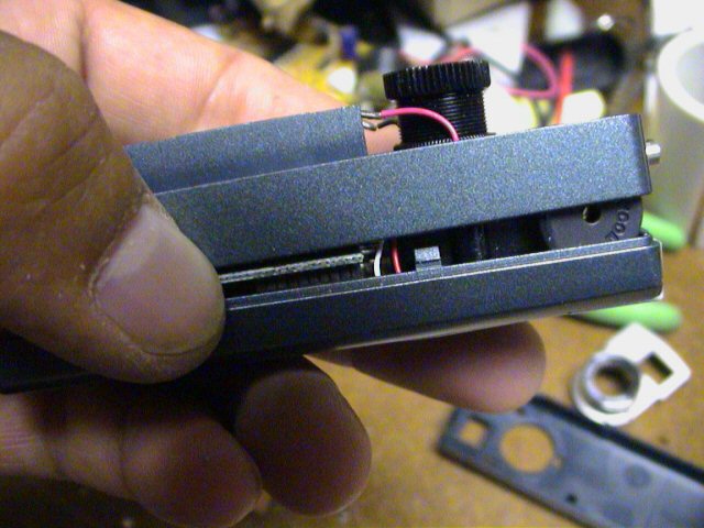
Once these screws are removed, you should be able to
detach the middle case section from
the lower case section. Be careful not to break any of the attached
battery wires. Simply rotate the middle case section and lay it along side
the bottom case section.
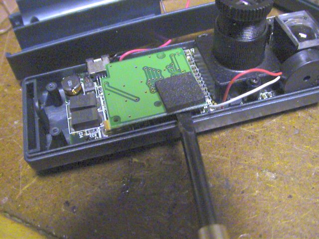
With the middle case section removed, locate the removable memory
card. I used a small plain screw driver to
gently pry the board up from its socket.
You can also gently grasp the board with your fingers and rock it back and forth
to remove.
NOTE: BE VERY CAREFUL IN REMOVING THIS AS "STATIC
ELECTRICITY" WILL RENDER YOU CAMERA USELESS !!. Ground yourself or better
yet, use a grounded ESD strap.
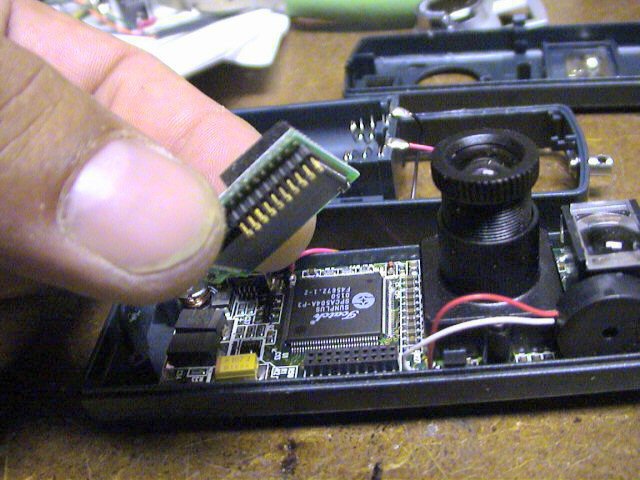
Once pried, gently remove
the memory board and place it in a safe non-static location (preferably a
anti-static bag). Without this daughterboard, you camera is useless.
Removing this memory board will gain you clear access to the USB connector.
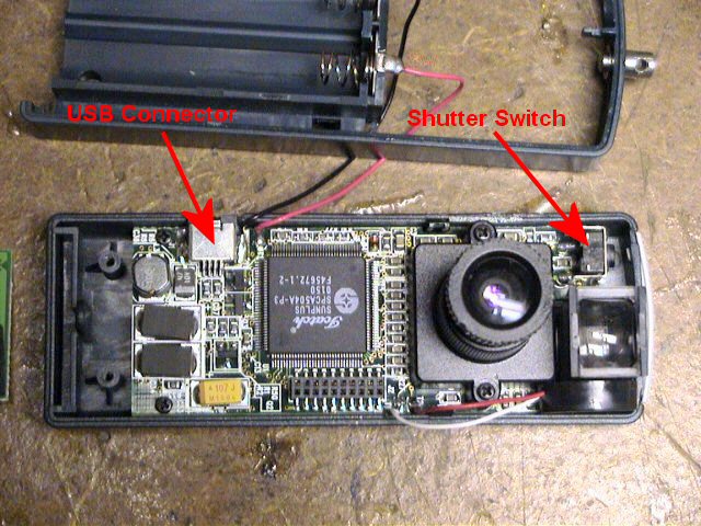
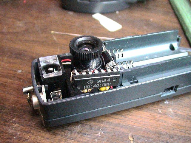
The picture to the left indicates
the location of the USB connector and the
camera's shutter switch connections. The shutter switch has two
connections, one to ground and one to the camera processor. We only need
to make a connection to the switch pin that is connected to the processor (the
pin closest to the outside of the camera).
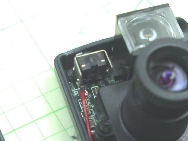 Using
a small piece of insulated wire and a small tipped soldering iron,
solder the wire to the switch connection
as shown. After soldering, you can test the connection by temporarily
installing the batteries, waiting for the camera to beep (powered and ready) and
then touching this wire to ground (the metal case part of the switch is fine).
If properly connected, this should force the camera to take a picture and beep.
Using
a small piece of insulated wire and a small tipped soldering iron,
solder the wire to the switch connection
as shown. After soldering, you can test the connection by temporarily
installing the batteries, waiting for the camera to beep (powered and ready) and
then touching this wire to ground (the metal case part of the switch is fine).
If properly connected, this should force the camera to take a picture and beep.
NOTE: To properly test, you will need to temporarily
reinstall the memory board first.
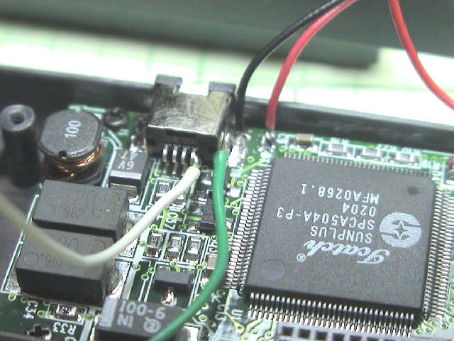
Next, connect two pieces of
wire to the USB connector. One wire will connect to ground (the metal
casing of the USB connector). The other connection can be a little tricky.
You need to make a connection to the outside pin (#1) of the USB connector.
You need to be VERY CAREFUL in making this connection as again, it can render
your camera useless. Such that you have adequate space, make the
connection to the USB pin first (then connect USB ground connection).
First, tin the end of your insulated wire and trim it such that the exposed
tinned wire is approximately 1/16". You can also dab a little flux onto
the USB pin prior to soldering. This will help facilitate the quick
soldering of the wire. Touch the tinned wire to the outside of the USB
pin, then gently apply your soldering iron to the tinned wire.
NOTE: DO NOT APPLY TOO MUCH PRESSURE TO THE WIRE/USB
CONNECTOR ! Doing so will most likely break the connection from the USB pin
to the camera board and you will then be unable to use the USB connector for
downloading pictures. Trust me,,, I have done this..... ONCE!.
Apply enough heat to the wire such the it gently connects to the
USB lead. After making this connection, you can again test the camera to
be assured it is still working properly (you might want to also check the USB
connector by attaching it to your PC and downloading pictures).
NOTE: To properly test, you will need to temporarily
reinstall the memory board first.
After being assured that it is connected and the camera is still
functional, make the ground connection to the USB metal case (you might have to
use some additional heat to get it to connect)... phew..... the tough part is
now done!
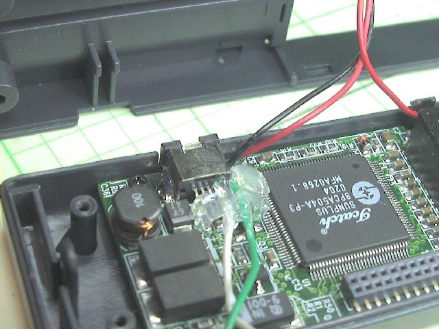
I usually then apply some
hot melt glue (or such) to the USB connection just to be certain that
excessive vibration does not bother the connection. I highly recommend
this step as it can not hurt. The glue will also allow you to manipulate
the wire without having to worry about breaking the connection or worse yet,
break the USB connection to the camera board.
Then, carefully reinstall
the memory board by aligning the pins/socket and gently press it into place
(press on the foam piece attached to the top of the memory board. Be careful not
to pinch the wires you connected. You should lead the wires out from under
the memory board, towards the location where the R/C switch circuit will be located (left side
of lens, just below the shutter switch)
Feed these wires through the middle case section as you reinstall
it, being careful not to pinch the wires. Be sure to properly reinstall
the silver plastic shutter button if it had fallen out during disassembly.
It simply fits into two pivot guides located on the middle case section.
Check its operation before continuing. Reinstall the
two tiny screws,
attaching the middle case section to the bottom case section.
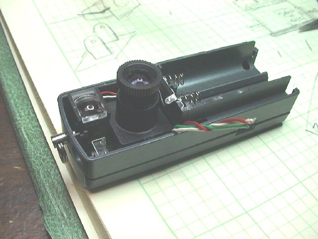
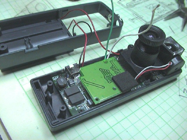
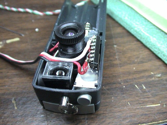
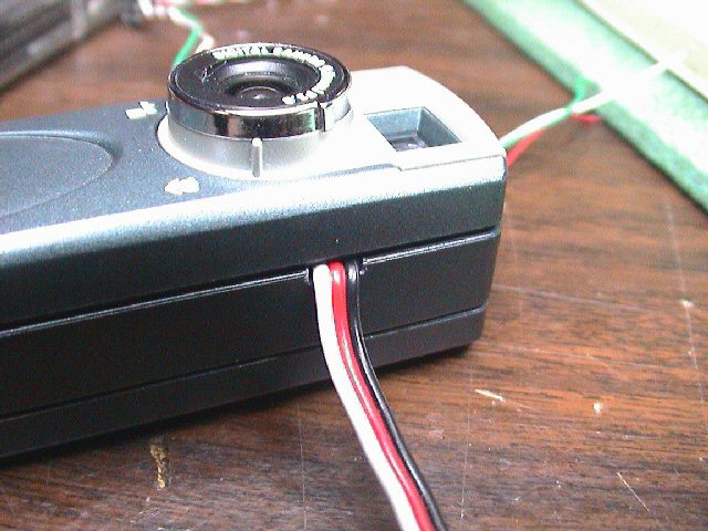
This picture is taken from another angle so that you can see
where the wires need to exit.
All we need to do now is assemble the circuit that will connect
to these three wires.
Take a break,... you are half way there!
 The
first step in building the circuit is to bend all the IC leads in toward the IC and snip off all the
long IC leads. Then using thin non-insulated wire (I used the leads I cut
off of components such as resistors and capacitors),
make the connections shown in "red".
The connections you need to make first are the ground connections that consist
of pins 6, 7, 8, and 10. I make these using one piece of wire. Then
make the connection connecting pins 5 and 14 (+V). After making these
connections, use thin insulated wire to make the "green" connections, connecting
pins 2 & 11, and pins 3 and 9 respectively. After this, connect the
resistor between pins 1 & 4, and then connect the capacitor between pins 4 & 7.
When adding these components, orient them such that they are right along side
the IC (see picture below). When
soldering to the IC, be sure to use minimal amount of heat else you will ruin
the IC. It is also probably best to tin each IC pin first before making
any connections. If at all possible, try to use a small clip-on heat sink
when soldering to the IC too (a simply clip-on alligator clip should suffice).
Take your time... have lots of patience. It is also very handy to have a
helping hand, such as another person of a mini bench-top holder/vise.
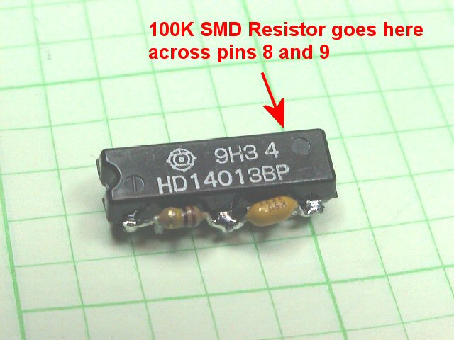
NOTE: It has been determined that in order to have
the camera properly operate with either batteries inserted or when connected to
your computer via the USB cable (i.e. not connected to your receiver), there must be a resistor placed across the servo
input lead and ground (between pins 8 & 9 on the IC). I used a small 100K SMD resistor and soldered it across the IC's pins, right along side the IC,
similar to the other resistor and capacitor. With out this pull-down, the
IC's pin will be allowed to float, occasionally triggering the camera's shutter, sometimes even causing the camera to lock up. I have had a few successes
with out the resistor but to be honest, you are better off adding it!
The
first step in building the circuit is to bend all the IC leads in toward the IC and snip off all the
long IC leads. Then using thin non-insulated wire (I used the leads I cut
off of components such as resistors and capacitors),
make the connections shown in "red".
The connections you need to make first are the ground connections that consist
of pins 6, 7, 8, and 10. I make these using one piece of wire. Then
make the connection connecting pins 5 and 14 (+V). After making these
connections, use thin insulated wire to make the "green" connections, connecting
pins 2 & 11, and pins 3 and 9 respectively. After this, connect the
resistor between pins 1 & 4, and then connect the capacitor between pins 4 & 7.
When adding these components, orient them such that they are right along side
the IC (see picture below). When
soldering to the IC, be sure to use minimal amount of heat else you will ruin
the IC. It is also probably best to tin each IC pin first before making
any connections. If at all possible, try to use a small clip-on heat sink
when soldering to the IC too (a simply clip-on alligator clip should suffice).
Take your time... have lots of patience. It is also very handy to have a
helping hand, such as another person of a mini bench-top holder/vise.
NOTE: It has been determined that in order to have
the camera properly operate with either batteries inserted or when connected to
your computer via the USB cable (i.e. not connected to your receiver), there must be a resistor placed across the servo
input lead and ground (between pins 8 & 9 on the IC). I used a small 100K SMD resistor and soldered it across the IC's pins, right along side the IC,
similar to the other resistor and capacitor. With out this pull-down, the
IC's pin will be allowed to float, occasionally triggering the camera's shutter, sometimes even causing the camera to lock up. I have had a few successes
with out the resistor but to be honest, you are better off adding it!
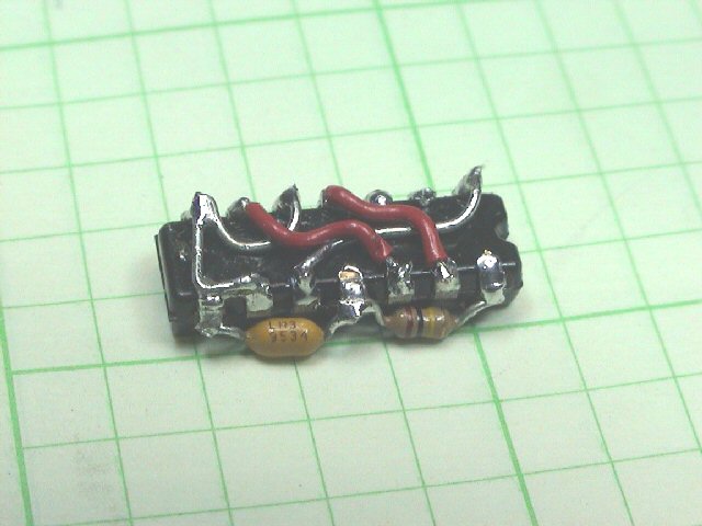
When completed, your R/C switch circuit should look like that of the
picture to the left. It might
look crude but if properly built, it should be fairly compact, just small enough
to easily fit in the Aiptek case.
At this stage if you want, you could hook up some temporary wires
and test the circuit. If this is your first R/C switch you built, it is
probably not a bad idea to test prior to continuing, just to have confidence
that it is wired correctly (and also to be certain the IC is still good!)
Here's another picture of the finished circuit (top
view).
Notice how snug both the resistor and capacitor are to the IC.
The capacitor pictured here is a small .022uF tantalum type capacitor; you could
also use a disc type but I believe they will be slightly larger in size.
I then cut a piece of thin
white cardboard such that it neatly fit inside the location where the R/C
switch circuit will reside. This acts as an insulator, protecting the R/C
switch circuit
against shorts.
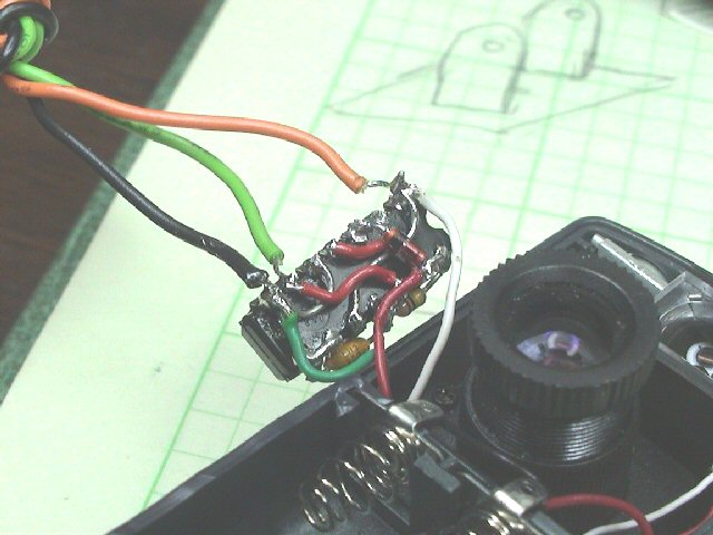
The R/C switch circuit is then
wired up appropriately, connecting the shutter wire (red wire) to the other
end of the diode, connecting the USB power wire (white wire) to pin #14, and
finally connecting the ground wire (green wire) to pin #8. (Granted, I
should had used red for +V, Green for ground and white for shutter switch... Oh
well, I already had them soldered to the camera board before I noticed this.. :(
)
I then connected a temporary servo wire to the circuit and
tested to be certain it was working properly (see black green and orange
wires in picture).
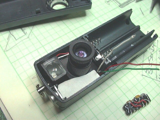
Here's another picture
showing where the R/C switch circuit is located in the camera. There's ample room
along the left side the lens, just below the shutter switch.
The permanent servo wire was then connected to the R/C switch
circuit (similar to
the servo wire used for testing as indicated above). I then
oriented the R/C switch circuit in its place
and applied a few drops of hot melt glue to hold it in place. The servo
wire will exit out of the opposite side of the camera case as shown in the
picture.
Using a razor blade, I then
notched out a small opening in the middle case section. After this, I
reinstalled the top case section. Before installing, be sure to adjust the
silver plastic focus ring so that it is fully clockwise (focus set to infinity).
This will insure that the focus setting is correct.
Reinstall the last remaining
screw, the screw you had first removed during disassembly which is located
under the battery door. Also, be certain the sliding battery compartment door is
properly in place before snapping the top case onto the camera.
YOU ARE NOW DONE!
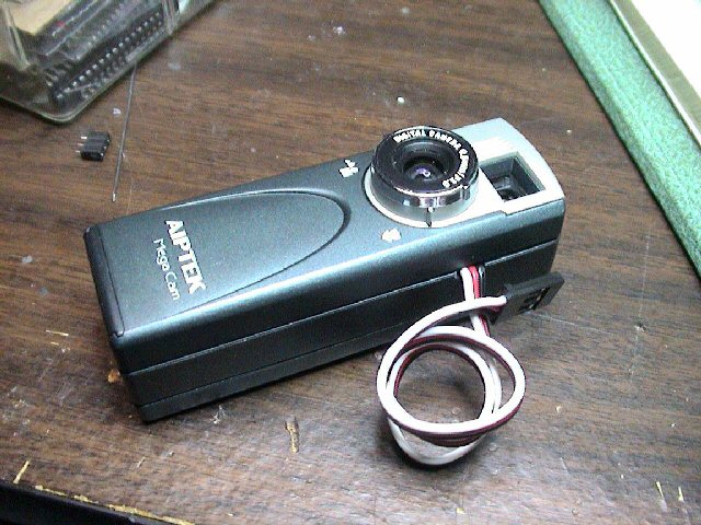
Here's a picture of the
completed modification.
Now it's time to test !!
Testing and Operation Instructions...
1) Turn on your transmitter
2) Plug the camera's servo connection into a channel on your receiver (I usually
use the throttle channel, Ch#3, for testing)
3) Connect a battery to the receiver. Upon connecting your receiver
battery, your camera should also power up, as indicated by a "beep".
4) If the throttle lever is set low and you do not hear any more beeps from the
camera, try toggling the throttle level (go from low to high, then back low).
If your circuit is working properly, you should here a "beep" from the camera,
indicating that it had taken a picture. Test a few times to be sure all is
working fine.
5) If after applying receiver power you hear the camera continually beeping, it
is indicating that the throttle position is causing the shutter switch to be
continually "On". Try alternating the throttle lever position (low to
high) and see if the camera beeping stops. If is does, you should be able
to toggle the throttle lever (high to low, then back to high) and hear the
camera beep once, indicating it had taken a picture.
Like most Aiptek cameras (and other small, cheap digital camera),
you need to pause approximately 4-5 seconds between taking pictures (the camera
needs time to save the picture to memory). If you do not pause enough time, you
will hear the camera beep fast, indicating a problem. Wait a few seconds
between taking pictures and you'll be OK.
Additional Notes...
There has been rare occurrences where an Aiptek camera can simply go
"berserk"...., i.e. continual beeping or just does not work at all (indicated
some times by all "eights" (888) in the camera display). In this case, it
is good to reset the camera by hold the "mode" button down
for a few seconds (until a beep is heard) while the camera is powered up. Removing
power and reapplying has some times fix the problem too.
If you do not like how the circuit operates (i.e. you would like
to reverse the operation such that the camera is triggered inversely in regards
to the control channel), you can either reverse the channel via your transmitter
(if it has that ability) or you can simply move the diode from pin #13 to pin
#12 (or vice-versa) on the R/C switch circuit. Either should work to your
satisfaction. You can also replace the 100K resistor to alter the R/C
switch operation in respect to a particular servo pulse/position. The 100K
resistor sets the position to be approximately 1/2 of the servo's throw position
(~1.5ms)
I have also noticed that when testing this setup with a 6 volt
receiver battery, the camera usually does not power up properly. If you
therefore plan to use a 5 cell receiver battery pack, you should also include a
5v voltage regulator in the design. I have built a few of these using a
surface-mount 8-pin (DIP) voltage
regulator.
Additionally, this modification
also allows you to use the camera as it was originally intended to be used.
You can simply unplug it from your receiver, throw 2 "AA" batteries in the
battery compartment and take picture using the original shutter button.
You can simply wrap the servo wire around the camera and put an elastic band
around it to keep it out of your way. How neat is that ???
I have also hacked many of these camera, completely removing the
case (saving weight) and wrapping the whole assembly (camera board and R/C
switch circuit) in heat shrink wrap. This makes for an even smaller and
lighter package (granted, you will then not be able to use it with batteries).
Click here to see a sample.
Good luck and hope this webpage was helpful!...
 NEW PCB STUFF.... UNDER CONSTRUCTION
 Here's
a new project that includes the designing of a PCB for the DIP circuit shown
above. Click on the links below to see more pictures. More to come
soon...
Here's
a new project that includes the designing of a PCB for the DIP circuit shown
above. Click on the links below to see more pictures. More to come
soon...
PCB
PCB#0
PCB#1
PCB#2
PCB#3
PCB#4
PCB#5
PCB#6
PCB#7
PCB#8
 Here's
a newer (?) project that includes the designing of a PCB for a Surface
Mount Device (SMD) version of the circuit shown above. Click on the links
below to see more pictures. More to come soon...
Here's
a newer (?) project that includes the designing of a PCB for a Surface
Mount Device (SMD) version of the circuit shown above. Click on the links
below to see more pictures. More to come soon...
SMD#1
SMD#2
SMD#3
SMD#4
SMD#5
SMD#6
SMD#7
SMD#8
SMD#9
SMD#10
SMD#11
SMD#12
SMD#13
And even with my failing eyesight,.. it actually works !

Earthmen
Productions
© Dec-00-Mar-12