AipAxe R/C Switch
Home
DIYRC STORE
About DIYRC.COM
What's New?
R/C Switches
Servo Projects
Tx/Rx Projects
LED Projects
Battery Projects
PCB Projects
Wireless Video
PIC Projects
Other R/C Projects
SOFTWARE
Favorite Links
Forums/Chat...
Photo & Videos
Customers
LIVE WEBCAM
Contact Us

03/30/2012
Earthmen Productions
© Dec-00-Mar-12


Home | Aiptek 1.3M Switch | AipAxe R/C Switch | AipAxe Installation | Aiptek-SD Switch | Maxi-Switch | Simple-Timer
Updated: March 30, 2012

"Aip-Axe"
Aiptek Digital Camera R/C-controlled Shutter Switch

History

Parts

Building

Firmware/Code

Testing & Operation

Notes

Note: All pictures that follow are "clickable".  Clicking on them will show you an enlargement!

PURCHASE AN "AIPAXE" R/C SWITCH  NOW!!
See how to install this in an Aiptek 1.3 SD Camera !
Download the User's Manual (PDF) !

A lil' history ...
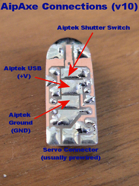
    As if we haven't seen enough Aiptek R/C switches, here is yet another, this time designed around a PIC microcontroller.    Since the design is based upon a Flash PIC (PIC12F683), you can continually download new code, allowing for experimentation and prototyping. 

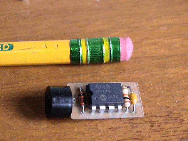
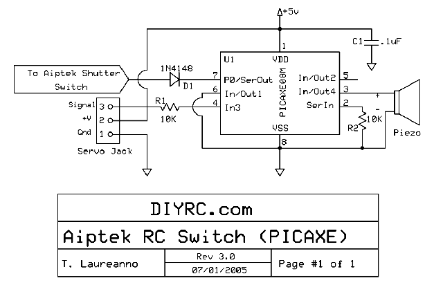
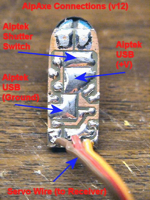
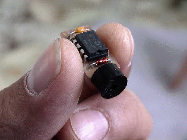
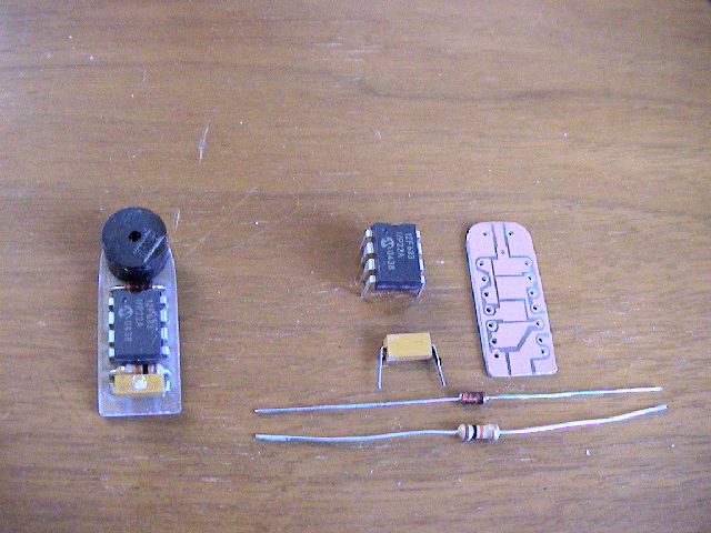
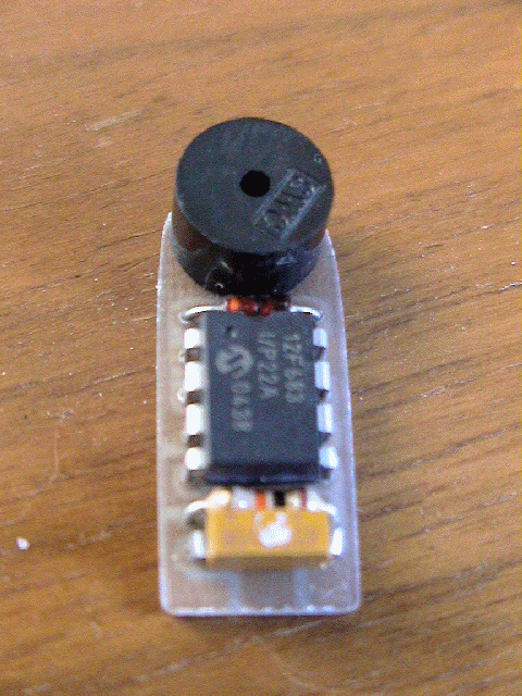
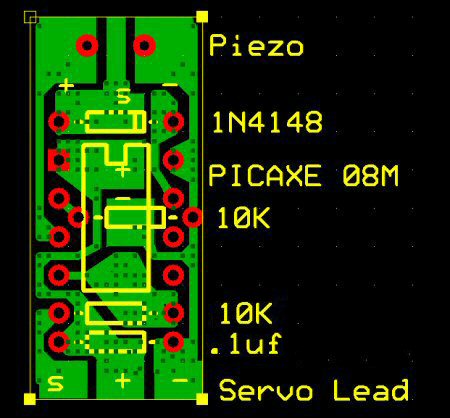
I designed this nifty circuit using a preprogrammed PIC microcontroller, a piezo element, two 10K ohm resistors, a .1uF capacitor and a 1N4148 signal diode.  This neat device allows you to program switch-on points and switch/stick direction.  The unit even stores the settings in internal memory.  If the circuit senses that there exists no servo signal, a piezo beeper is sounded.  This can be used as a model-finder.  Next time your plane gets lost in the high grass, you can simply turn off your transmitter and a second later, the beeper continually emits beeps, allowing you to locate the downed plane.  The circuit also has a built in trigger delay that does not allow the Aiptek camera to attempt to take pictures faster than it can store them to memory.  These user-programmable functions are very easy to use.

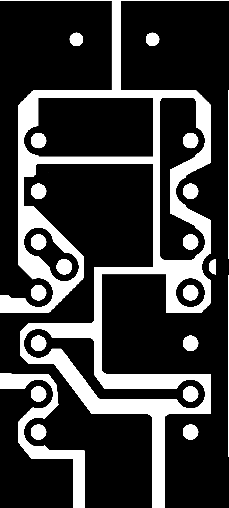
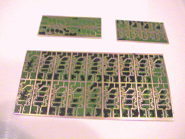
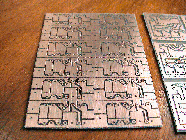
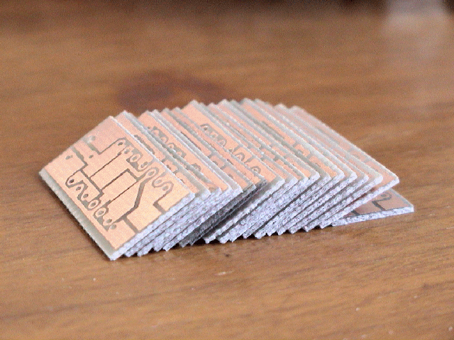
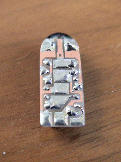
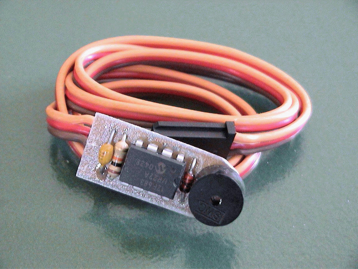
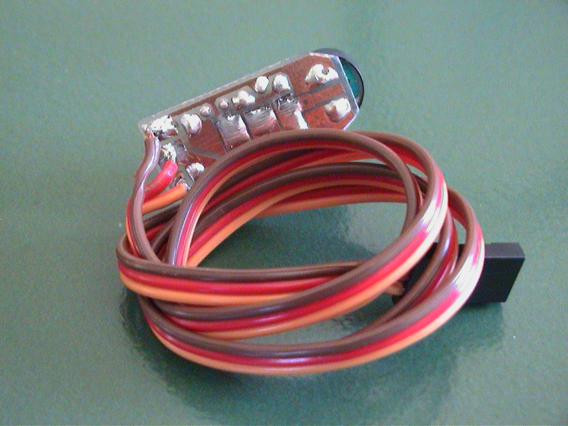
Newer pictures !! (new circuit/PCB design as shown below)

..more coming soon


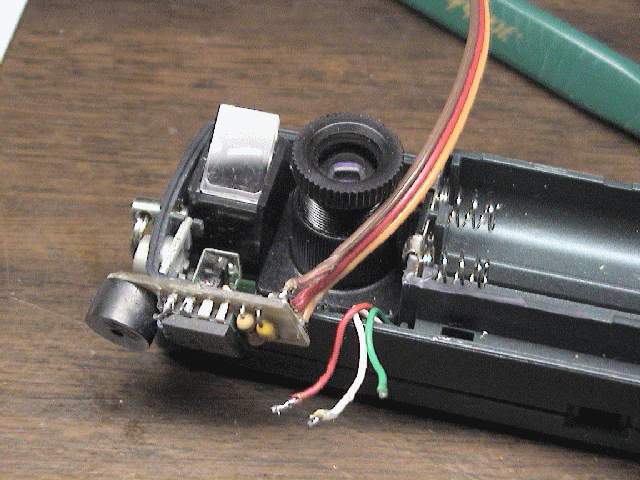
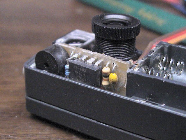
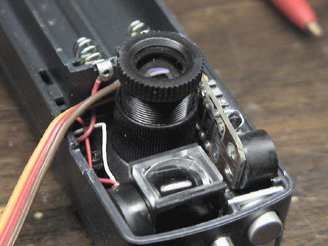
Below are a few pictures that show you how this AipAxe switch installs in an Aiptek 1.3M digital camera...
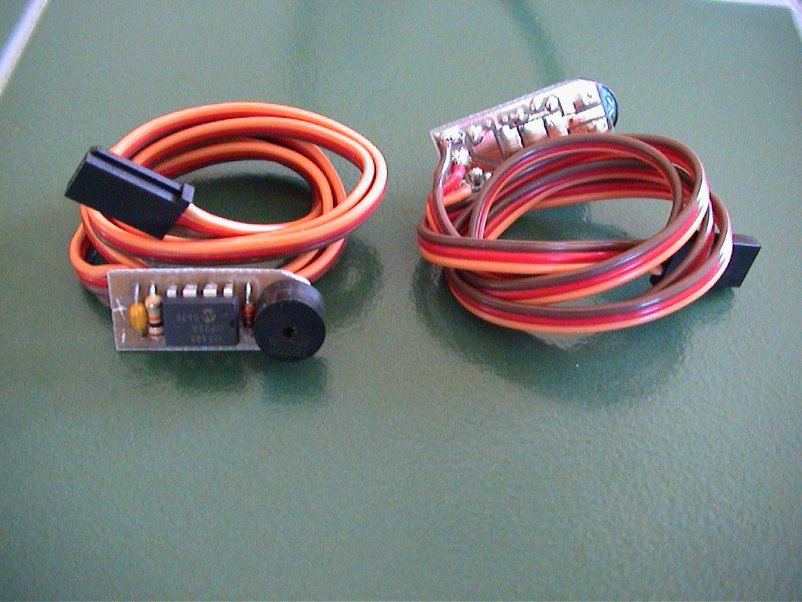


Older pictures are shown below (Version 1):


See how to install this in an Aiptek 1.3 SD Camera !
 

Design Criteria Summary:

1) ...more coming soon

Parts & Tools List ...

1) ...more coming soon

Building Instructions...

...more coming soon


Firmware/Code...

Click here to View Code (Sorry, firmware is no longer freeware)

Click here to Download Code (Sorry, firmware is no longer freeware)

CHECK BACK LATER.... I WILL BE ADDING FREE CODE "SNIPPETS" !!


Testing and Operation Instructions...

DOWNLOAD THE USER'S MANUAL (MS WORD)

DOWNLOAD THE USER'S MANUAL (PDF)


OPERATING INSTRUCTIONS

1. With both the transmitter and receiver powered off, plug the camera's servo plug into the receiver channel # to which you want to use as your shutter control.  This can either be a switch or joystick.

2. Power up the transmitter first and position the switch or stick (corresponding to channel on receiver which switch is connected) in the direction to which you would want to be the OFF position (the position where no picture is taken). 

3. Now power up the receiver and you will hear the switch and Aiptek camera eventually power up (beeps).  About a second or two after that (as the circuit analyzes the receiver servo signal), you will hear a "Ready" beep (2 low beeps then a longer high beep) indicating that the circuit is ready for operation (no others beeps should be heard until you take a picture).

IS THAT SIMPLE ?

4. To take a picture, move the joystick/switch to the On position and then return it to the opposite (OFF) position.  You should hear the switch circuit output a low to high chirp, and then quickly hear the Aiptek camera take a picture (also visible on the Aiptek display).  If the transmitter's switch/joystick if left in the ON position, the switch circuit will make the Aiptek camera take a picture approximately every 7 seconds, until the switch/joystick is returned to the OFF position.

5.  If you were to turn off the transmitter while the receiver and camera are powered up, the switch circuit will eventually continually beep, indicating that there exists no servo signal.  This is the built-in "Model-Finder" alarm that will hopefully help you locate a downed aircraft.  Just power off the transmitter and the circuit will begin to beep.

6. Upon powering up the transmitter, you will eventually hear a "Ready" beep (2 low beeps then a longer high beep) indicating that the circuit is ready for operation once again.


Additional Notes...
 
bullet

Aiptek cameras can be funny in that some are particularly sensitive to input voltage.  Most Aiptek cameras I have modified work fine on 5V and even 5.5 volts.  If you try to power up the camera from the receiver and the receiver is powered using 5 cells (6 volts), the camera will probably not turn on, and you in fact might damage the PIC switch circuit. Some work, some don’t.  It is highly recommended that you power up the receiver/camera using either a 4 cell battery pack (4.8-5.2 volts) or use a Battery Elimination Circuit (BEC) or voltage regulator that outputs a regulated 5 volts.
 

bullet

When you connect the camera up to your computer to download pictures (via USB cable), the camera and switch circuit are powered up.  Because the circuit senses NO servo signal, the model-finder alarm will beep continuously as you are downloading pictures.  The download process is not affected by this beeping.  Once the downloading is complete, simply unplug the USB cable from the camera.
 

bullet

This mod originally was designed such that the camera could still be powered and operated with two AAA batteries.  After modifying a bunch of these cameras, I have noticed that some work normally with batteries installed but some do not.  I therefore can not guarantee that the camera will operate properly with batteries installed.  The intention of this modification was to make an R/C controlled aerial camera using a miniature hand-help digital camera.  I can guarantee that this mod will do just that!
 

bullet

There has been rare occurrences where an Aiptek camera can simply go "berserk"...., i.e. continual beeping or just does not work at all (indicated some times by all "eights" (888) in the camera display).  In this case, it is good to reset the camera by hold down the "mode" and "shutter" buttons simultaneously for several seconds until a beep is heard (do this while camera is powered up).  Removing power for  a few seconds and reapplying has some times fix the problem too.

TRICKS!  The AipAxe chip was originally designed to output a High-Z state when not triggered, but when trigger, the output pin is driven to 0v (or ground)... this ground is what triggers the Aiptek camera shutter switch.  If you want the PIC's output to provide +5v when triggered, you can connect pin#6 to +5v (preferably through a 10K resistor).  Normally on the camera switch PCB I sell, this pin is grounded by default.

Additionally, as designed, the PIC will toggle the output (from 0 to 5v or from High-Z to Ground.. depending on Pin#6 state described above) every 7-8 seconds.  Upon being triggered, you’d have to wait 7-8 seconds to re-toggle the output.  The PIC's pin#5 controls the delay of this toggle function... when grounded, you get a 8 second delay and when connected to +5v (though 10K resistor), you would have a 1 second delay.


**** VERY LIMITED QUANTITIES ARE AVAILABLE ****
Please email me regarding product availability before sending money....

Click Here to visit the


Earthmen Productions
© Dec-00-Mar-12

horizontal rule

horizontal rule


Home | Aiptek 1.3M Switch | AipAxe R/C Switch | AipAxe Installation | Aiptek-SD Switch | Maxi-Switch | Simple-Timer

Home | DIYRC STORE | About DIYRC.COM | What's New? | R/C Switches | Servo Projects | Tx/Rx Projects | LED Projects | Battery Projects | PCB Projects | Wireless Video | PIC Projects | Other R/C Projects | SOFTWARE | Favorite Links | Forums/Chat... | Photo & Videos | Customers | LIVE WEBCAM | Contact Us

This site was last updated 03/30/12