A lil' history ...
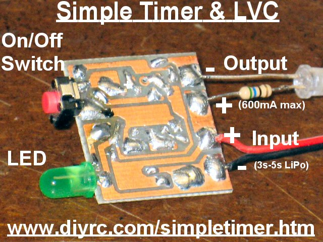
 This project, called
"Simple-Timer" is a programmable
Timer and electronic switch with an integrated LiPo Battery Monitor that is based
around a PIC microcontroller. This idea grew out of a
RCGroups.com discussion shown here. You can use this timer/switch to
control something (set-on/timed-off) such as a free-flight
airplane motor or another load which needs to be turned off after the
timer has expired (maximum of 600mA with PN2222 transistor or higher
if a MOSFET is used) . The
"Simple-Timer" includes a fairly accurate
timer that is programmable (via pushbutton) by the user and can be programmed to time
a 5, 10, 15, 20,25 or 30 minute event. When the timer/switch is enabled
(tap small pushbutton), the onboard LED indicates the output is
active by lighting solid (the circuit also outputs the same voltage as your supply/battery
voltage using a PN2222 NPN transistor or a high current MOSFET). When the timer expires,
both the onboard LED and the switched output is turned off.
As if this timer/switch functions is not enough features, the
"Simple-Timer" also includes a a neat user-programmable
LiPo Battery monitor or Low Voltage Cutoff (LVC). The
"Simple-Timer" circuit includes a
5 volt voltage regulator (78L05) and is used to regulate the battery
voltage (11.1v-18.5v) down to 5 volts which is used to power the
This project, called
"Simple-Timer" is a programmable
Timer and electronic switch with an integrated LiPo Battery Monitor that is based
around a PIC microcontroller. This idea grew out of a
RCGroups.com discussion shown here. You can use this timer/switch to
control something (set-on/timed-off) such as a free-flight
airplane motor or another load which needs to be turned off after the
timer has expired (maximum of 600mA with PN2222 transistor or higher
if a MOSFET is used) . The
"Simple-Timer" includes a fairly accurate
timer that is programmable (via pushbutton) by the user and can be programmed to time
a 5, 10, 15, 20,25 or 30 minute event. When the timer/switch is enabled
(tap small pushbutton), the onboard LED indicates the output is
active by lighting solid (the circuit also outputs the same voltage as your supply/battery
voltage using a PN2222 NPN transistor or a high current MOSFET). When the timer expires,
both the onboard LED and the switched output is turned off.
As if this timer/switch functions is not enough features, the
"Simple-Timer" also includes a a neat user-programmable
LiPo Battery monitor or Low Voltage Cutoff (LVC). The
"Simple-Timer" circuit includes a
5 volt voltage regulator (78L05) and is used to regulate the battery
voltage (11.1v-18.5v) down to 5 volts which is used to power the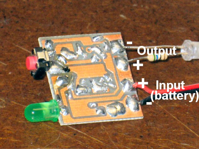 Simple-Timer circuit. The LVC setting is also programmable by
the user such that it can work with LiPo packs ranging from 3s to 5s
configurations, or any voltage in between. When the
voltage of the battery drops below this preset cutoff voltage, the
circuit will stop the
current timer (opening switch) and will quickly flash the onboard LED
indicating LVC has been reached. The Simple-Timer will continue
flashing its LED until power is removed. This programmable LVC
alarm allows for a visual indication that the battery is depleted to a
point that you need to stop drawing power from it. If you were to drain the
battery pack below it's voltage cutoff point, you can and will probably ruin
your LiPo pack.
Simple-Timer circuit. The LVC setting is also programmable by
the user such that it can work with LiPo packs ranging from 3s to 5s
configurations, or any voltage in between. When the
voltage of the battery drops below this preset cutoff voltage, the
circuit will stop the
current timer (opening switch) and will quickly flash the onboard LED
indicating LVC has been reached. The Simple-Timer will continue
flashing its LED until power is removed. This programmable LVC
alarm allows for a visual indication that the battery is depleted to a
point that you need to stop drawing power from it. If you were to drain the
battery pack below it's voltage cutoff point, you can and will probably ruin
your LiPo pack.
A
video of its operations is here:
http://www.laureanno.com/RC/Simple-Timer-LVC1.wmv
Read more about the
Simple-Timer's operation by viewing the
Simple-Timer User's Manual ! (Rev 1) -
Under Construction
Design Criteria Summary:
1) Design a simple and affordable programmable timer
with integrated switch and Low Voltage Cut-off (LVC) circuitry, based around 8-pin PIC
2) Design so timer is programmable (5-30 minutes) using pushbutton
3) Lightweight and small in size
4) Provide an integrated LiPo Battery Monitor (visually indicate issues by
quickly flashing all LEDs)
5) Provide a switched output (same as supply) that is capably of 500mA
(using MOSFET instead of PN2222A increases current
capability)
6) Provide a pushbutton switch for on/off operation
8) Allow programming of LVC setting (so it can be used for 3s-5s LiPo packs)
Parts & Tools List
...
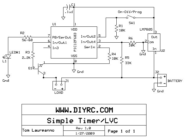
1) One
(1) PIC12F683 programmed with Simple-Timer hex code
2) One (1) PN2222A NPN Transistor or high-current MOSFET
3) One (1) 2.2K ohm Resistor
4) One (1) 33K ohm Resistor
5) Three (3) 10K ohm Resistor
6) One (1) 56-100 ohm Resistor (for LED, depends on input voltage)
7) One (1) .1uF Capacitor
8) One (1) 78L05 5v Voltage Regulator
9) One (1) Green 5mm LED
10) One (1) Pushbutton Switch
Building Instructions...
 BUILDING
INSTRUCTIONS FOR THE SIMPLE-TIMER KIT !
BUILDING
INSTRUCTIONS FOR THE SIMPLE-TIMER KIT !
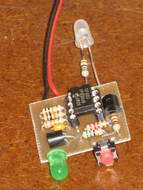
Some pics:


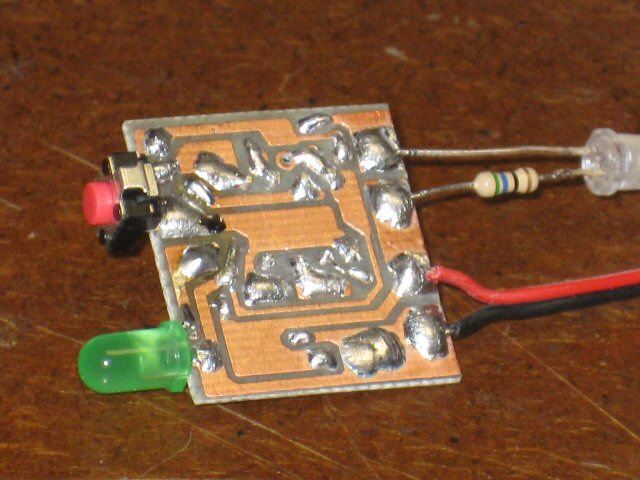
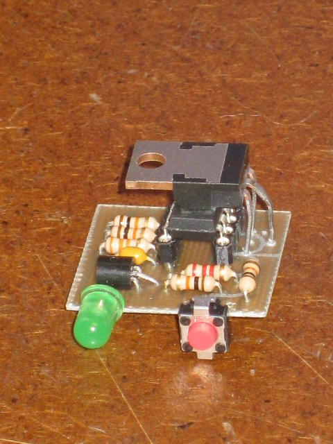
SORRY... NOT YET FOR SALE!
Simple-Timer & LVC - (Assembled/Tested with no
wires)
Programming Software...
THE PICAXE FIRMWARE FOR THIS PROJECT IS NOT FOR SALE ....
SORRY
 Pre-programmed
Picaxe chips are now available !
Pre-programmed
Picaxe chips are now available !
Click here to purchase
one now!
Testing and Operation Instructions...
(Online User's Manual)
The
Simple-Timer has an input (Battery, 6v to 22 volts) and an output (switched
output same as input voltage). The Simple-Timer also incorporates a neat
Low-Voltage Cutoff (LVC) feature that will not let you over-discharge your LiPo
battery. The timer delay and the cut-off voltage is programmable by the
user using the pushbutton but only during certain times/sequences... thus making
it difficult to accidentally reprogram either value.
Normal Startup of the Simple-Timer/Switch
Upon power-up, the green LED lights up for around a 1.5 seconds and
after that, it blinks a # of times indicating the current delay time (once=5min,
twice=10min, 3x=15min, 4x=20min, 5x=25min and 6x=30min). At this time, the
circuit is waiting for you to either enable or disable the timer/switch. You
control this on/off operation by tapping the pushbutton. When you first tap the
button, the LED lights indicating the timer and switch is enabled (load/output
is supplied the input voltage via transistor). To turn the switch/timer off,
simply tap the button again, and you should see the LED go off (load/output
turns off). You can repeat the on/off process indefinitely, until the LVC is
detected.
Setting/Programming the Timer Delay value
(5 - 30 minutes, #1-6 blinks)
Changing the timer's delay value is easy. Upon power-up, the
green LED comes on solid for about 1-1/2 seconds. During this 1-1/2
seconds, you need to tap the button the # of times corresponding to the delay
value (same as above). After this tapping, you should see the circuit display
the delay value again (blinks # of time in regard to the delay setting). Once
this delay is set, it is always read from memory every time it is powered up.
Example: You want to set the timer for 20 minutes. That is setting
#4 (5, 10, 15,20). You then power up the timer/switch and while the green
LED is On, you tap the pushbutton 4 times in a row. A second or so later,
the LED should blink 4 times indicating it is set for setting#4, or 20 minutes!
Operation of the Integrated Low Voltage Cut-Off (LVC)
Function
The LVC function is active when the switch is either on or off (protects
battery). When the programmed LVC point (see below) is detected, the circuit
turns off the timer and both the LED and load, and then continually flashes
(fast rate) the green LED indicating the LVC has been triggered. The only way to
clear this LVC indicator is to remove power to the circuit (you will not be able
to turn on/off the LED/switch during this LVC indication).
Setting/Programming the LVC point
Another neat feature incorporated is the ability to change/set the low voltage
cutoff (LVC) point. By default, this setting is 9 volts (3s LiPo). To change
this setting you would power-up the circuit using a voltage you want to use as
the cut-off, while holding in the pushbutton (purposely tough to do such that
you do not alter this by mistake). When you do this (button held in then power
applied), the LED will immediately light up for a second, where you can then
release the button. The circuit then reads the current supply voltage and uses
this voltage as the LVC setting (saved in memory). Now, if you were to remove
power and reapply, the circuit should operate normally but now with the new LVC
setting.
I plan to add more information re: this neat gadget
as time allows.
 TWO
OF THESE UNITS ARE BUILT AND ARE CURRENTLY BEING BETA TESTED !!!
TWO
OF THESE UNITS ARE BUILT AND ARE CURRENTLY BEING BETA TESTED !!!
SIMPLE-TIMER/LVC FAQ
Q1. .
A1. ...
 |
TBD
|
|
TBD |
**** VERY LIMITED
QUANTITIES ARE AVAILABLE ****
Click Here to visit the


Earthmen
Productions
© Dec-00-Mar-12
