Note: All
pictures that follow are "clickable"

CLICK HERE TO SEE A VIDEO OF THE EASY-FLASH CONTROLLER
IN ACTION!
and Yes!,... it'll run off of a single 3.7v LiPo cell!
(watch the video here!)
Assembly Instructions
User's Manual-Download
or View
BUY ONE NOW!
A lil' history ...
 This
project, called "Easy-Flash", is a miniature
programmable LED Sequencer/Flasher that is based around the PIC microcontroller. The
Easy-Flash
is a programmable, 2 LED channels sequencer that also incorporates Radio Control
(R/C) functions. These functions allow the Mini-Flash to be used for
scale, navigation lighting and even night-time flying! The user at any
time can reprogram the LED sequencer using a simple jumper. The main
objective of this project was to design a small light weight LED controller
fro small R/C models such as the new micro helicopters that have recently
surfaced in the R/C market. This design was originally developed using a
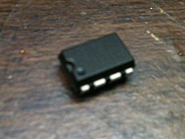
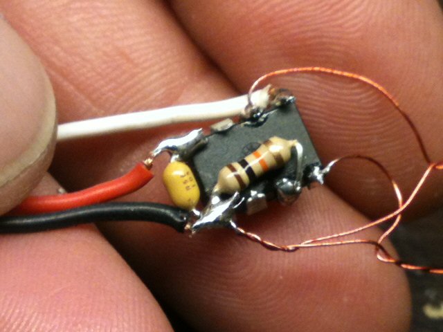
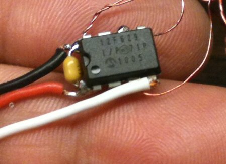
DIP size PIC (pictured to left) but could easily be adapted to use smaller
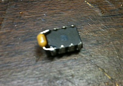
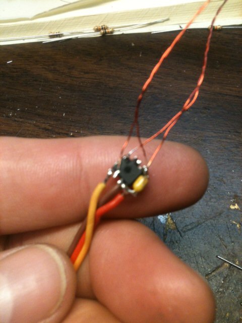
surface mount components (I built one... tedious but very small and weighs a
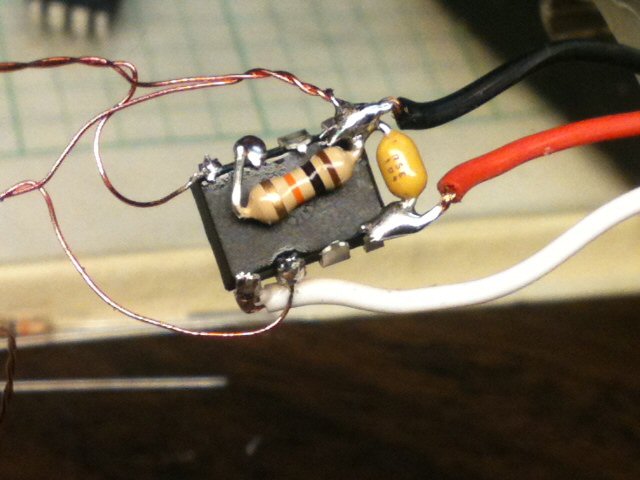
feather). As shown in the picture above, the DIP version only needs one
resistor and one capacitor. The resistor, capacitor, LED and power wires
are soldered directly onto the PIC's pins, hence no printed circuit boards (PCB)
is needed. Upon building you could simply encapsulate the PIC in a blob of
epoxy to keep the wires intact.
This
project, called "Easy-Flash", is a miniature
programmable LED Sequencer/Flasher that is based around the PIC microcontroller. The
Easy-Flash
is a programmable, 2 LED channels sequencer that also incorporates Radio Control
(R/C) functions. These functions allow the Mini-Flash to be used for
scale, navigation lighting and even night-time flying! The user at any
time can reprogram the LED sequencer using a simple jumper. The main
objective of this project was to design a small light weight LED controller
fro small R/C models such as the new micro helicopters that have recently
surfaced in the R/C market. This design was originally developed using a
DIP size PIC (pictured to left) but could easily be adapted to use smaller
surface mount components (I built one... tedious but very small and weighs a
feather). As shown in the picture above, the DIP version only needs one
resistor and one capacitor. The resistor, capacitor, LED and power wires
are soldered directly onto the PIC's pins, hence no printed circuit boards (PCB)
is needed. Upon building you could simply encapsulate the PIC in a blob of
epoxy to keep the wires intact.
Design Criteria Summary:
1) Design a simply and cheap programmable LED
flasher around 8-pin PIC
2) Design so LED sequencing speed and sequence pattern is programmable
3) Lightweight and simple to build (DIY)
4) Power off of existing R/C servo connector
5) Use servo signal to vary how each LED channel responds (turn programmed
pattern on or off)
6) Powers two 5-10mm LEDS (25-20mA per channel), directly from PIC (no output
transistor)
WANT TO BUY A PRE-PROGRAMMED & TESTED
EASY-FLASH CONTROLLER PIC?
Easy-Flash Controller -
Pre-Programmed PIC Only
(This is for one pre-programmed PIC only... no other
parts)

CLICK HERE TO BUY ONE NOW !
LIMITED SUPPLY !
Parts & Tools List
...
1) One
(1) PIC12F629 Chip (preprogrammed with Easy-Flash code)
2) One (1) 10K ohm resistors (not needed after programming the pattern you want)
3) One (1) .1uF Tantalum Capacitor
4) One (1) Servo Lead/Pigtail wire for Mini-Flash
(Note: Customer is
responsible for supplying LEDs and connecting wires...
LEDs are sold separately
in the DIYRC webstore... CLICK HERE!)
Building Instructions...
* EASY-FLASH BUILDING INSTRUCTIONS *
CLICK HERE TO VIEW THE BUILDING INSTRUCTIONS FOR THE MINI-FLASH

The following procedures should be used to build your Easy-Flash circuit.
1)
2)
3)
Programming...
THE PIC FIRMWARE CODE FOR THIS PROJECT
IS NOT FOR SALE .... SORRY
The user can program one of twelve (12) possible LED flashing patterns.
The first 6 are 3 speeds of alternating blinking LEDs (1, 3 and 5 are single
flashes while 2, 4 and 6 are double flashes) while the last 6 are 3 speeds of
alternating rotating strobe like LEDs (7, 9 and 11 are single top flashes while
8, 10 and 12 are double top flashes).
The user can set the program by applying a jumper between +5 volts (pin 1 on the
PIC) and the PICs pin#4. Pin#4 is normally connected to ground via the 10K
resistor. By applying +5 volts to pin#4, you "pull it up" to a high level,
telling the controller to advance to the next pattern. When shorted to
+5v, all LEDs will glow onstantly until you remove the jumper. Upon
removal, you will see the LEDs flash the # of times indicating the new pattern
number now selected. You can continue jumping pin#4 to =5V to keep
advancing the pattern# you like this value is stored in memory such that
every time you power up the PIC, it uses this stpred value as the pattern #.

Testing and Operation Instructions...
*
EASY-FLASH USERS' MANUAL
*
CLICK HERE TO VIEW THE USERS'
MANUAL FOR THE EASY-FLASH
*
EASY-FLASH USERS' MANUAL
(PDF)
*
CLICK HERE TO DOWNLOAD THE USERS'
MANUAL FOR THE EASY-FLASH
I plan to add more information re: this neat gadget
as time allows.
MINI-FLASH FAQ
Q1. How do you compensate for
differing forward voltages and current drawn by differing LED's?
A1. Ah.... good question....
The input voltage to LEDs is all not that important (usually 5v is fine for
all). It is the current that you push through the LED that is important, as you
do not want to drive them with too much current. You usually always need to put
a series resistor inline with one of the LED leads such to limit the current. I
use a neat calculator, I even have a link for it on my webpages. You really need
to know the specs on the LEDs, particularly the LEDs rated current (typical 5mm
LEDs run around 20-25 milliamps). Here's the calculator:
http://linear1.org/ckts/led.php
You simply enter the supply voltage (in the
controller's case, 5 volts), the LEDs forward voltage (this varies from LED to
LED) then enter the rated LED current (typically 20-25 milliamps). Then hit the
"find R" button and the program calculates the resistor value you need for that
LED (typically a 68-120 ohm resistor is required). Be careful also as there
exists some LED that already have the series resistor incorporated in the LED
(not all that common though). Once the resistor value is determined, I
usually then solder it to the end of one of the LED leads. The wires then
leading from this LED assembly is then connected directly to the controller
using a miniature machine-pin female socket (I will provide at least 8 with
every controller). Putting the series resistors on the PCB would take up
space (unless they were SMD maybe).
Q2. ...
A2. ....
Additional Notes...
**** VERY LIMITED
QUANTITIES ARE AVAILABLE ****
Click Here to visit the


Earthmen
Productions
© Dec-00-Mar-12